Introduction VaporTEK Controller
14
VaporTEK Controller
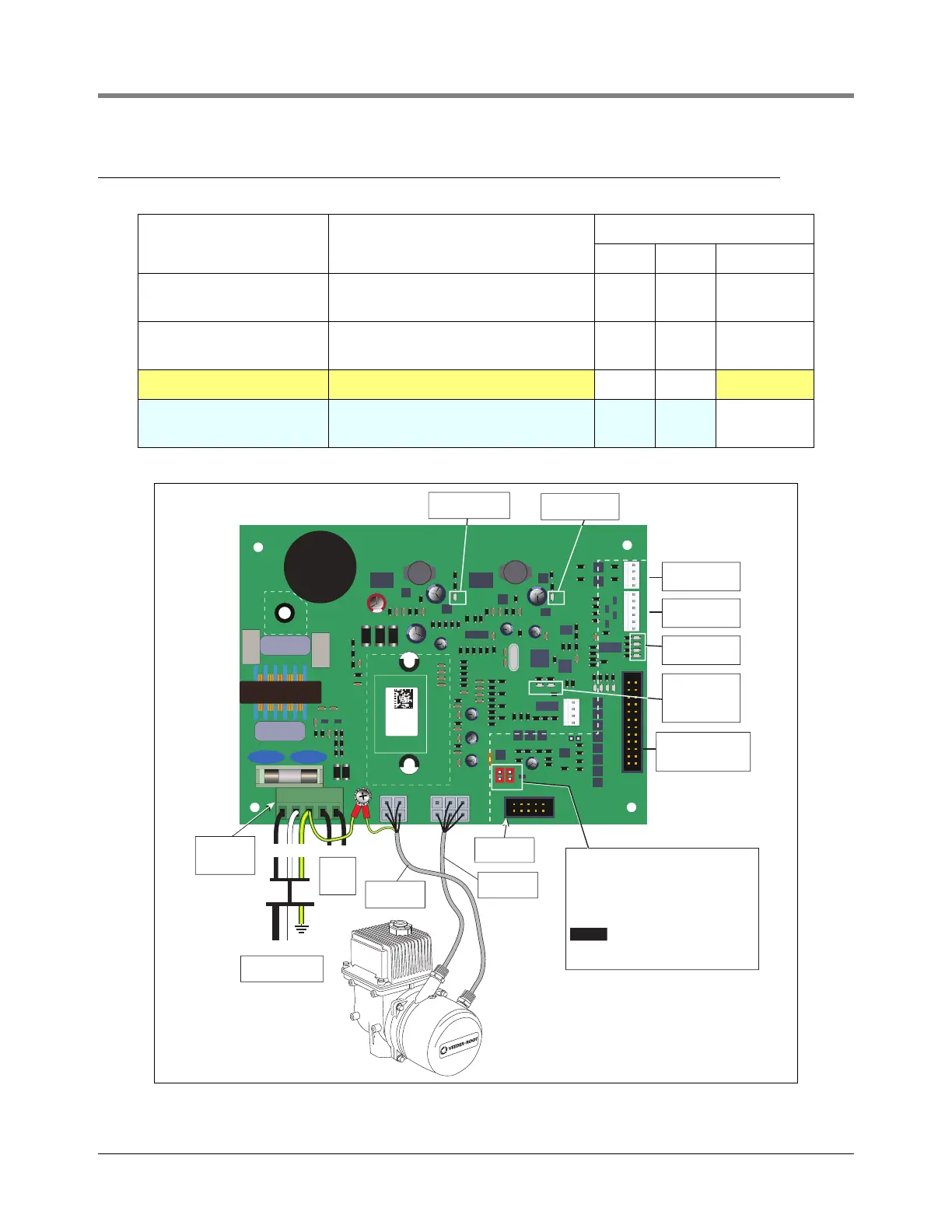
Figure 4. VaporTEK-3 Controller Board Connections
Configuration Type VaporTEK Controller Mode
Mode Selection
J1 J2 J3-PROG.
VaporTEK Basic
VaporTEK Plus
Two-speed system, high voltage hook sig-
nals are required
No No No
VaporTEK Enhanced
VaporTEK Ultra
Electronic signal of fuel flow required No No No
Board Programming Mode Power OFF/ON cycle required No No Yes
VaporTEK Enhanced
VaporTEK Ultra
VaporTEK - master mode with monitoring
system and re-regulation
Yes Yes No
VEEDER-ROOT
VAPORTEK-CONTROLLER
900890-001
Rev.C
P/N 141 031 916
S/N 0000586
DATE 49/2016
RoHS Compliant
PE
F1
PE
L N PE M1 M2
+ - AB SB AA SA EPV VALVE
MOTOR
POWER
MOTOR
SIGNAL
J3
V6
V3 V8
V1
X7
X6
X8
PROGRAM
J1
J2
X3X2
X1
X4
BR1
IC5
RS422
L1 N
L1 N
PE
High
Voltage
Inputs
AC - Main Power
110V - 230V
Main Power
Connector
X1
Motor Power
Cable
Motor Signal
Cable
To VaporTEK-3
Pulse Interface
Adapter Board - X8
Board Heartbeat
LED - V3
Motor/Board
Error LED - V8
Monitor Status
LEDs
External LED
Connector - X7
External EPV
Connector - X6
J1/J2 Jumper Setting - RS422 Serial
J1 and J2 need to be placed to establish
monitoring communication with re-
regulation using the X4 - RS422
interface.
NOTICE Do not place these jumpers if a
Master device like SK700-2 or Appolo
Calculator is connected to that interface!
5V Board Logic
Power LED - V6
15V Motion Chip
Power LED - V1
UNSAFE AREA
UNSAFE AREA
SAFE AREA
RS422 Serial
X4
M1 M2