Installation Alternate VaporTEK-3 Controller Board Mounting
24
Alternate VaporTEK-3 Controller Board Mounting
This procedure is required when installing the VaporTEK-3 Controller board in the dispenser electronics
compartment as a standalone component.
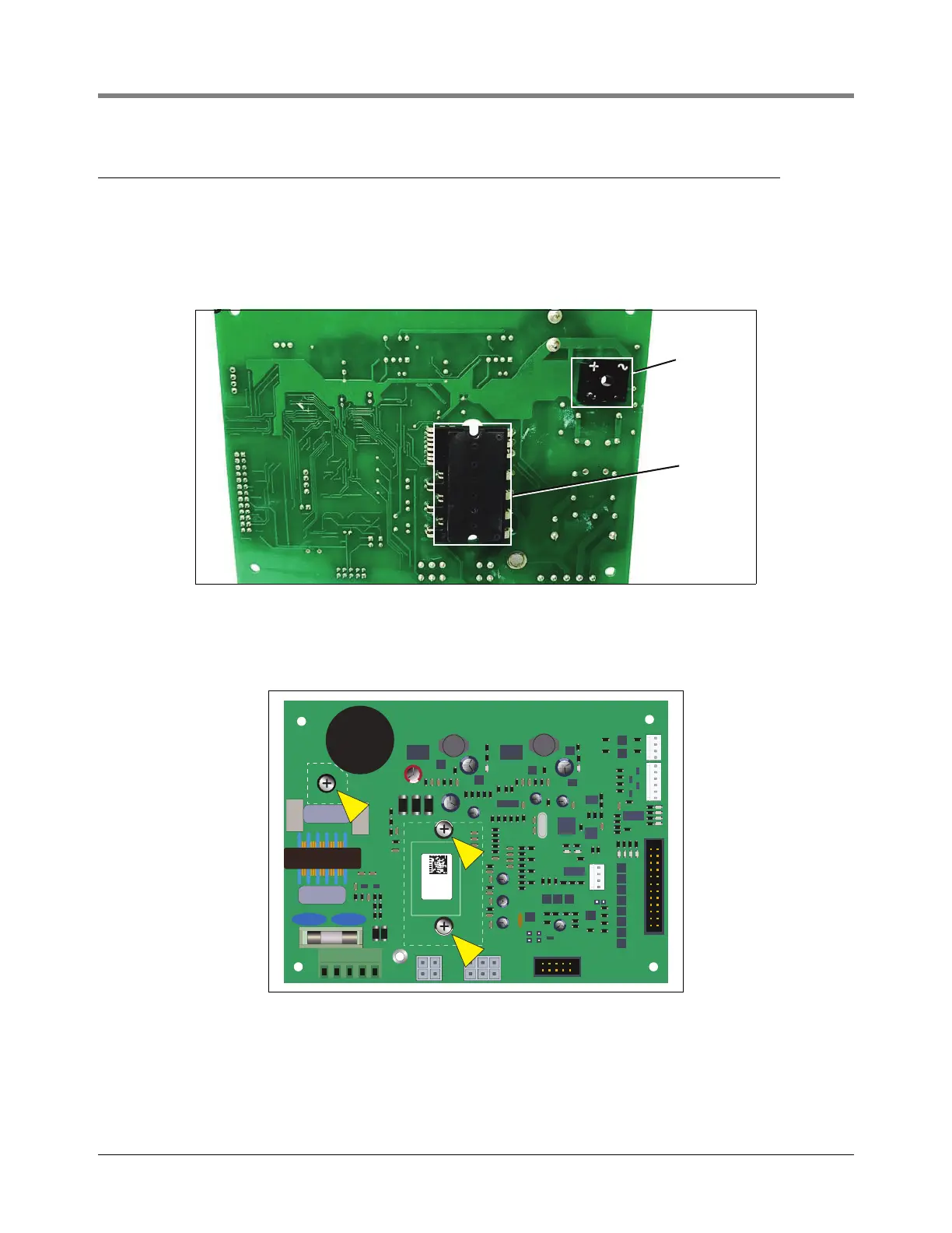
1. Prior to mounting the board onto a sheet metal surface of the electronics compartment, paint the bottom
surface areas of the board’s motion controller and rectifier chips (Figure 12) with a thin film of thermal transfer
paste (NTE303 or equivalent).
Figure 12. Apply Thermal Transfer Paste To These Component Surfaces
1. Fasten the VaporTEK-3 Controller board to the mounting surface with three M3-0.5 X12 long screws, and
three M3-0.5 tooth washer hex nuts, (see Item 1, Figure 3). Torque each screw to a nominal 0.60 N-m (min.
0.50 N-m / max. 1.00 N-m).
Figure 13. Apply Thermal Transfer Paste To These Component Surfaces
VEEDER-ROOT
VAPORTEK-CONTROLLER
900890-001
Rev.C
P/N 141 031 916
S/N 0000586
DATE 49/2016
RoHS Compliant
PE
F1
PE
L N PE M1 M2
+ - AB SB AA SA EPV VALVE
MOTOR
POWER
MOTOR
SIGNAL
J3
X7
X6
X8
PROGRAM
J1
J2
X3X2
X1
X4
BR1
IC5
RS422
1
1
1