OTDR Series e-Manual, D07-00-076P-RevC00 Page 74 of 107
Pulse Width: Select 1-10 pulsewidths that you wish to use to build V-Scout Link Map by
checking Enabled. An asterisk will mark any Pulse Width that you have already selected for
use in your new test plan.
Resolution: Choose Auto or manually select the available resolution you desire. (Options will
vary with distance range).
Time per Trace: Select the time to use in each test. (The more pulsewidths, the longer the
total test time will be). For record keeping, using short test times is not recommended test
times. Bellcore recommends up to 3 minutes per test.
When the V-Scout test plan is complete and OTDR traces performed, the operator can view
the V-Scout link map.
To set up and use the automated V-Scout mode:
1. Select the Autosave parameters in the Test Setup tab. See the Autosave Parameters
section for more details.
2. Tap the green Start button. Elapsed time and acquisition wavelength is indicated below the
red Stop button.
3. When the acquisition is complete, the Stop button will revert back to a green Start button.
If needed, tap Stop to terminate the measurement manually.
4. To view the results, select the V-Scout tab.
7.1.4.2 V-Scout symbols
The V-Scout Icons facilitate quick fiber diagnosis so that technicians can fix issues quickly and
efficiently ensuring fast turnaround time and reduced truck rolls.
The table below summarizes the symbols used to represent various events on the fiber link.
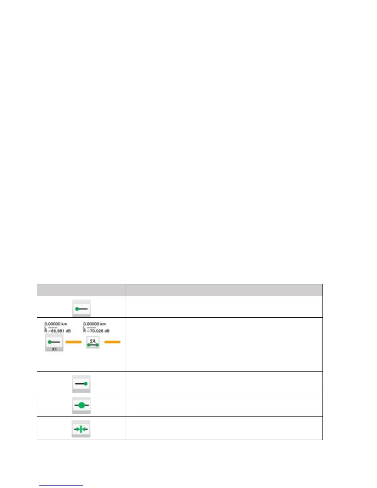
Span start (indicates start of analysis section) – as defined in
Test Setup
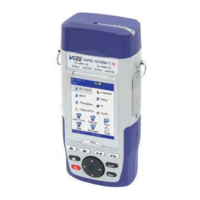
X1(2)(3) means ONE (or 2 or 3) merged events followed by
“short patchcord” icon
Xxxx km Distance to the node
L ---- Loss cannot be measured
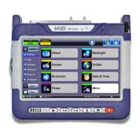
Span end (indicates start of analysis section) – as defined in
Test Setup (distance or event index)
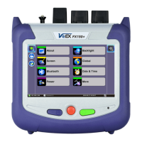
Splice
Loss >0.01 dB, Reflectance <-50 dB
Connector
Loss >0.05 dB, Reflectance > -50 dB