3
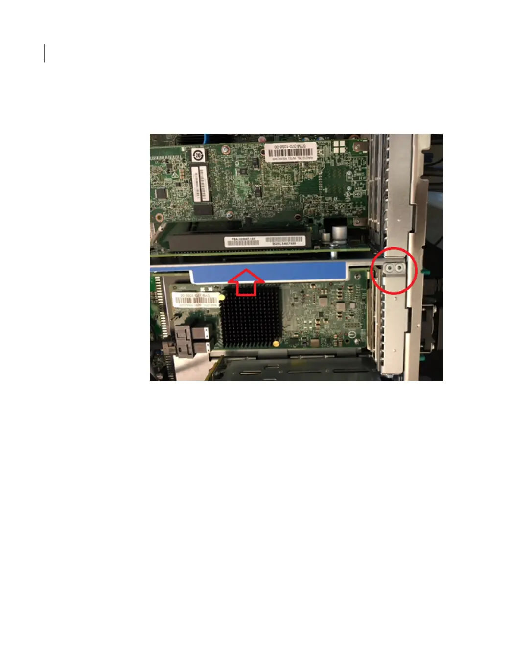
Locate the two rivets that hold Risers 2 and 3 together. These risers are
removed from the chassis as one unit. The circled rivets in the picture show
the connection site of the two risers. Do not separate the risers.
4
Hold the blue frame (indicated by the arrow) and lift it up from the main board.
5
Be careful not to damage any PCIe cards or HBA cards that are already installed
in riser 2 and riser 3.
6
Locate three components of riser 2.
■ The screw that secures the External RAID PCIe card in riser 2.
■ The socket in slot 1 on riser 2 into which the External RAID PCIe card is
inserted.
■ The gold pins at the bottom of the riser which fit into the socket on the main
board.
Adding one or more storage shelves to an operating 4TB appliance that does not have any storage shelves
Installing the External Storage Kit components
80
 Loading...