Vertiv™ | Liebert® AHU | User Manual 35
To Power-On the Unit:
1. Press then > Turn Unit On, then Unit On dialog box opens.
2. Press Turn Unit On, then the cooling unit starts, and the operating status is displayed as shown in Figure 3-4.
No. Description
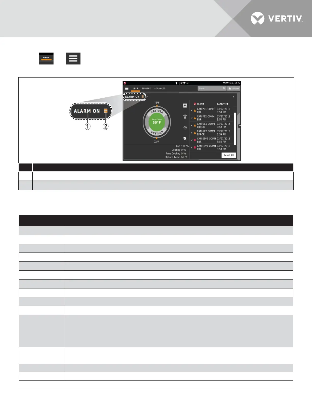
1 Current status of the unit. See Cooling -unit status displayed as follow.
2 Teamwork icon. See Viewing Teamwork, Stand-by, Cascade Status.
Figure 3-4 Unit Status on iCOM Display
Table 3-3 Cooling Unit Status Displayed
Unit Status Text Description
ALARM OFF
An alarm forced the unit to turn o. See Viewing Unit Alarm.
MANUAL
Controlled by a service technician.
DISPLAY OFF
Unit is turned OFF at the iCOM display. See Powering-on the Thermal Management Unit.
ALARM STANDBY
In stand-by because of an active alarm on the unit see Viewing Unit Alarm.
STANDBY
In stand-by, because of service menu setting.
TIMER OFF
Scheduled on a timer and is in “sleep” mode waiting for the next start interval.
UNIT ON
Operating normally without alarm or warning.
WARNING ON
Active warning but still operating.
ALARM ON
Active alarm but still operating.
TIMER
Scheduled on a timer to operate and is in operating mode.
REMOTE OFF
• Turned-o by remote shutdown terminal.
• Occurs when a normally-closed set of 24 V contacts open.
• The remote On/ O and Display On/ O switches are in series, and the cooling unit will only turn-
on if both switches are “On/ Closed” or if one is “O/ Open”, the unit turns o.
MONITORING OFF
• Turned-o by remote monitoring system.
• Check the remote monitoring device or call Vertiv technician support for assistance.
BACK-DRAFT
Unit is non-operational, but EC fan is operating as a back-draft damper.
RESTART DELAY
Not yet operational after a power cycle because the restart- delay time is active.