Assembling bevel gearbox
Assembling bevel gearbox
Assembling bevel gearbox
Assembling bevel gearbox
Assembling bevel gearbox
Assembling bevel gearbox
Assembling bevel gearbox
Assembling bevel gearbox
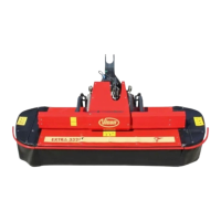
Tools : Snap ring pliers, pipe,
hammer, fork wrench n°13-17-19-22,
torque meter, dynamometric wrench,
comparator.
• In order to test the right mesh
between gears, use a color like
Prussian blue on the gear’s
teething.
• Assemble snap ring (5) using
pipe and hammer inside cover
(3), assemble outer ring (7).
• Assemble pre-mounted cover (3),
bolts (4) and tighten manually.
• Check assembled axis preload
value (K) using a torque meter.
• Disassemble cover (3) and snap
ring (5).
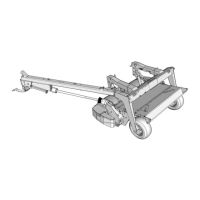
• Put a Silicone film between
housing and cover contact faces.
• The backlash value must to
be 0.10÷0.28 mm.
• In order to have the correct
backlash, change shims
setting (6), (pls be aware that
when you change the shims
set, you also will have to re-
set the preload).
• Disassemble bolts (4), cover
(3) and put a Silicone film
between housing and cover
contact surfaces.
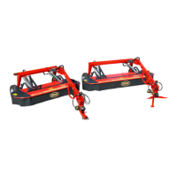
• Assemble cover (3), bolts (4)
and tighten to 5÷6.5 kgm.
• Assemble shim (6), snap ring
(5) and re-assemble cover (3).
• Hit shaft (1) from both sides in
order to set the axis.
• Check assembled axis
preload value (W) using a
torque meter.
• The difference between value
(W) and value (K) must to be
1÷7 Kgcm.
• If the value is not correct
change shim setting (6) in
order to obtain the right value.
• Rotate manually shaft (1) in
the work direction and lock the
pinion shaft (18).
• Verify the right mesh between
gears, (see the technical
specifications on page 11).
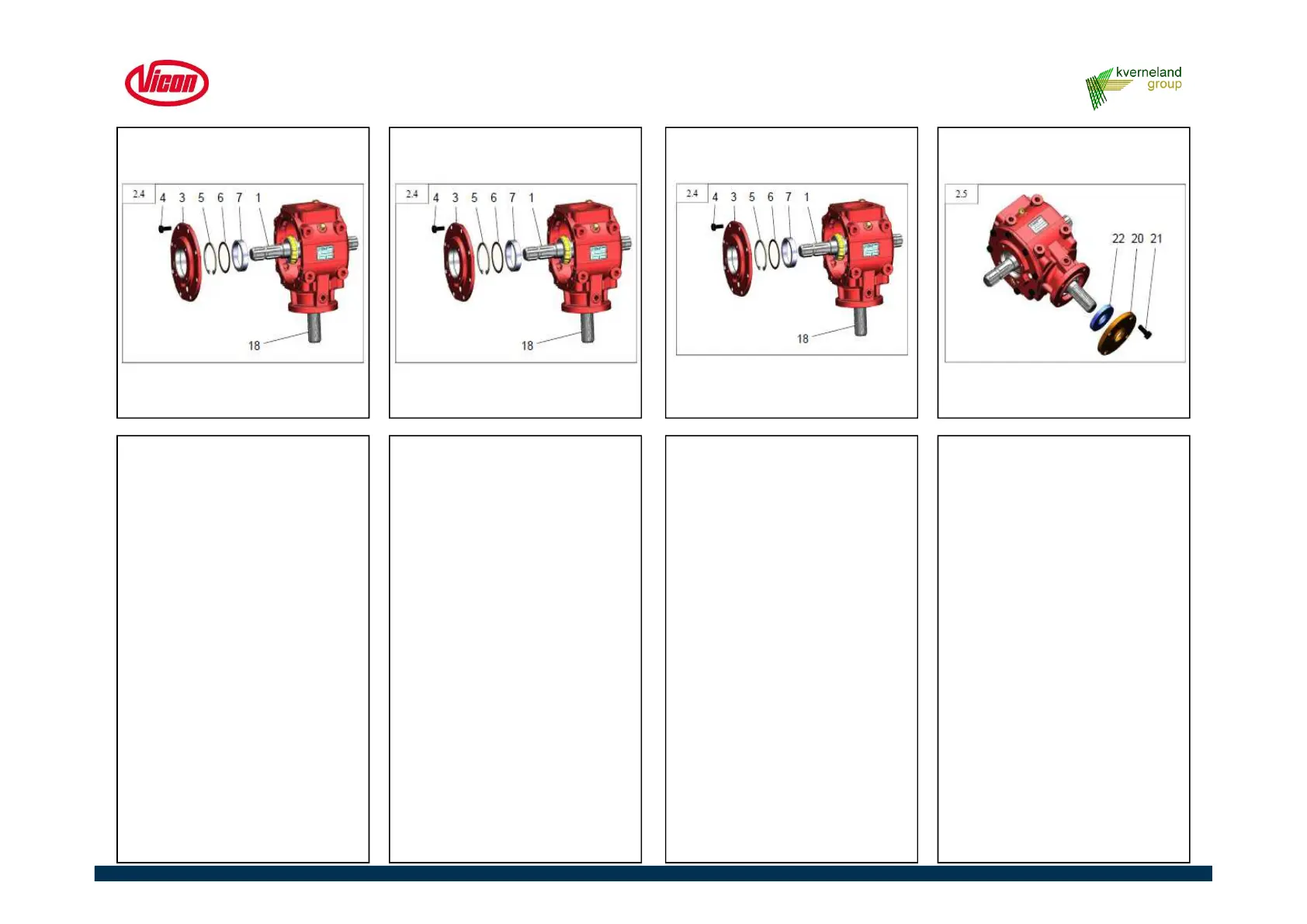
• Assemble oil seal (22), using
pipe and hammer.
• Assemble cover (20), bolts
(21) and tighten to 8.5÷10.9
kgm.
4.7 Repair of Gearbox machine side
55
 Loading...