10
NOTES AND SUGGESTIONS
FOR A CORRECT INSTALLATION
On the previous page are shown some examples but the combination
of modules can be different for the same number of push buttons.
A front panel for 5 apartments, in addition to the example shown, can
also be obtained as follows:
A) Art. 837-1/.. + Art. 844 /..
B) Art. 837-2/.. + Art. 843/..
It is always useful to remember that the maximum number of call but-
tons are as follows:
N° of Modules N° of calls
(includ. door ampl) (Max)
1 - - - - - - - - - - - - - - - - - - - - - - - - - - - - -2
2 - - - - - - - - - - - - - - - - - - - - - - - - - - - - -7
3 - - - - - - - - - - - - - - - - - - - - - - - - - - - -12
4 - - - - - - - - - - - - - - - - - - - - - - - - - - - -17
6 - - - - - - - - - - - - - - - - - - - - - - - - - - - -27
9 - - - - - - - - - - - - - - - - - - - - - - - - - - - -42
As previously stated the back boxes can be connec-
ted by using the plastic spacers provided and, the-
refore, it is possible to obtain panels with more than
42 push buttons. In this case to use the covering
frame, rainshields or the surface mounting units it will
be necessary to make groups of panels (max 3 rows
each group).
To reach exactly the number of call buttons using the
acquired configuration it could be very useful to use
the Blanking Module Art. 840 and the Information
Module Art. 846.
The Blanking Module, in particular, is very useful in
case of future modification from standard door entry
system to video intercom system (4+1 system without
coax cable).
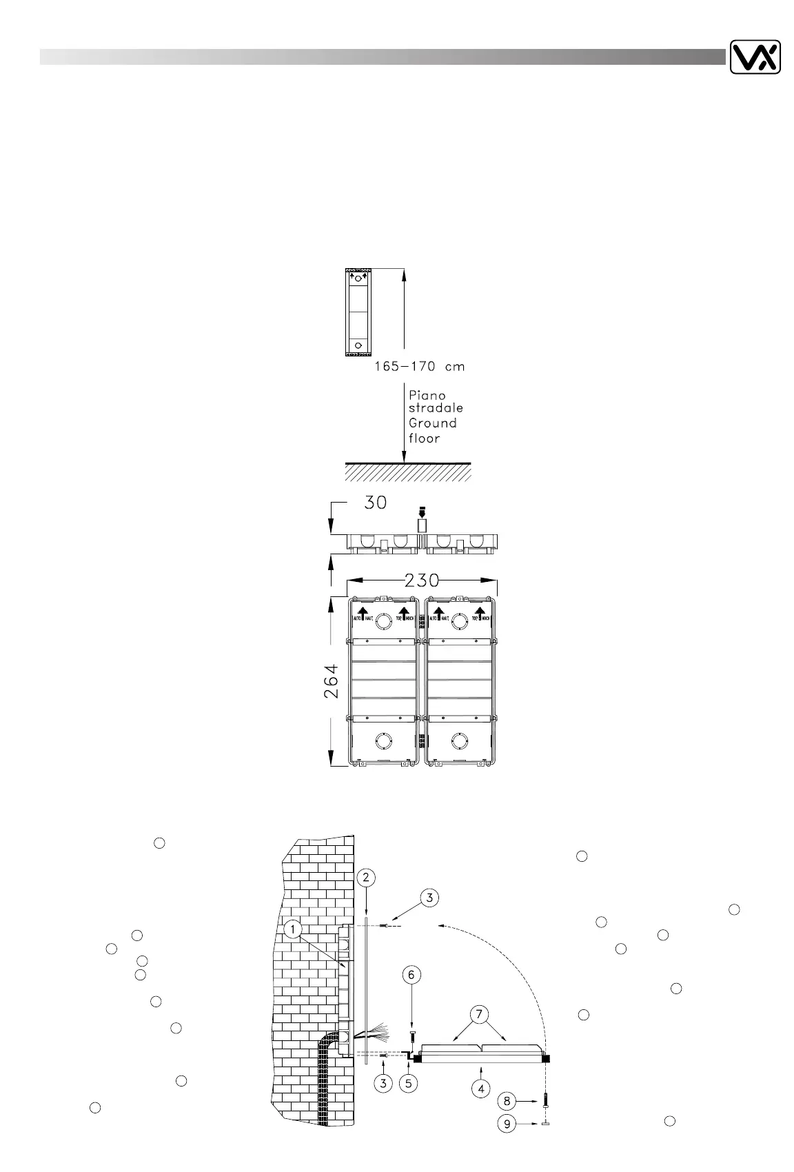
Mounting procedure of a front plate
with 2 modules.
- Set in back box 1 at 165-170 cm
from ground level (height recommen-
ded for installations using camera
modules) ensuring that all fixing holes
for modules support and accessories
are cleanly and accurately finished.
- In case of use, fix the covering frame
(or rainshield) 2 by using the screws
provided 3 .
- Insert modules 7 into the sliding gui-
des of support 4 , insert lamps provi-
ded in the proper lamp holder.
- Insert the hinge 5 into the proper
guide of back box and fix by the
two screws provided 6 .
- Carry out connections accurately
using wiring diagram provided.
- Rotate the support upwards and fix to
back box using screws 8 provided.
- Mask the screw by using plastic
cover 9 provided.
NOTE E SUGGERIMENTI
DI INSTALLAZIONE
Per alcuni esempi riportati, la combinazione dei moduli può essere
diversa anche per uno stesso numero di chiamate.
Un impianto citofonico per 5 utenti, oltre all'esempio riportato nella
pagina precedente, si può anche combinare:
A) Art. 837-1/.. (con 1 tasto) + Art. 844/.. (con 4 tasti)
B) Art. 837-2/.. (con 2 tasti) + Art. 843/.. (con 3 tasti)
In ogni caso si può riepilogare che il numero massimo di chiamate
ottenibili, su tre file é il seguente:
N° Moduli N° Chiamate
(Compreso portiere elettrico) (Massimo)
1 - - - - - - - - - - - - - - - - - - - - - - - - - - - -2
2 - - - - - - - - - - - - - - - - - - - - - - - - - - - -7
3 - - - - - - - - - - - - - - - - - - - - - - - - - - -12
4 - - - - - - - - - - - - - - - - - - - - - - - - - - -17
6 - - - - - - - - - - - - - - - - - - - - - - - - - - -27
9 - - - - - - - - - - - - - - - - - - - - - - - - - - -42
Per un numero di chiamate superiore a 42 si possono
ulteriormente affiancare, utilizzando gli appositi
distanziali passacavo in dotazione, altre scatole da
incasso e sostegni portamoduli; in questo caso se si
prevede il montaggio di accessori come cornici o tet-
tucci antipioggia o scatole per montaggio filomuro,
occorre separare i moduli in due o più gruppi .
L'utilizzatore può scegliere, in relazione al numero di
utenti, la configurazione desiderata o la disposizione
su più file di moduli. A questo scopo risulta utile l'uti-
lizzo del Modulo Neutro Art. 840 e del Modulo
Informazione Art. 846.
Il Modulo Neutro in particolare, risulta utile per preve-
dere una futura trasformazione dell'impianto citofoni-
co in videocitofonico (sistema 4+1 senza cavo Coax).
Esempio di montaggio pulsantiera a due
moduli.
- Murare attentamente la scatola incasso
1 , a 165-170 cm.dal piano stradale
(altezza raccomandata per moduli video)
evitando di otturare i vari fori.
- Eventualmente fissare la cornice in allu-
minio (o tettuccio antipioggia) 2 con le
viti 3 .
- Infilare i moduli 7 nel supporto porta-
moduli 4 , inserire il microfono nella sua
sede ed inserire le lampade in dotazione
negli appositi portalampade.
- Infilare la cerniera 5 nella scanalatura
della scatola incasso e fissarla con le viti
6 .
- Eseguire i collegamenti seguendo gli
schemi d'installazione , collaudare l'im-
pianto e regolare i volumi.
- Ruotare il supporto portamoduli verso
l'alto e fissarlo alla scatola incasso con la
vite .
- Coprire la vite di chiusura tramite il
tappo in plastica 9 .
 Loading...