Vigilant MX1-Au Operator Manual Document: LT0439
Page 23 October 2018 Issue 1.73
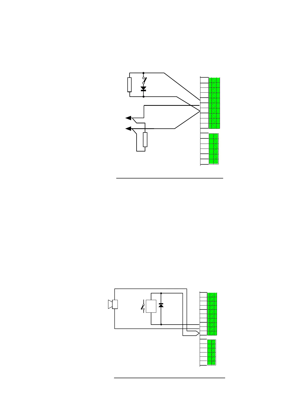
If supervision is not required, the ELD can be omitted.
The MX1 site-specific configuration must have appropriate input
supervision modes and zone mapping for these inputs to produce any
effect. There is no default action.
M
X1 CONTROLLER
2k7
A N C R E L A Y 1
VBF +
OUT 1
OUT 2
IN 1
IN 2
0 V
2k7
N/O
N/O
CLEAN
CONTACTS
Figure 11-16 – Wiring General Purpose Inputs
MX1 has two protected open collector outputs which can be used for
driving low-current loads, e.g., external buzzers or relays.
Figure 11-17 shows examples of connection to a fault buzzer and an
external relay. The maximum load current is 500mA for each output, i.e.,
54 minimum load resistance. The relay back-emf suppression diode
can be any general purpose diode such as 1N4004.
Each output can be configured for open circuit fault detection if this is
required.
The MX1 site-specific configuration must have output logic or a zone
mapping for these outputs to operate. There is no default action.
VBF +
OUT 1
OUT 2
IN 1
IN 1
0V
Buzzer
Relay
MX1 MICROCONTROLLER
ANC RELAY 1
+
-
Figure 11-17 – Wiring General Purpose Outputs
General
Purpose
Outputs
(OUT1,
OUT2)