Document: LT0439 Vigilant MX1-Au Operator Manual
Issue 1.73 23 October 2018 Page 11-25
The I-HUB comes pre-configured for ring operation, with Port 5 (J4)
connected to the MX1 serial port configured for networking.
Figure 11-21 – Network Ring Example
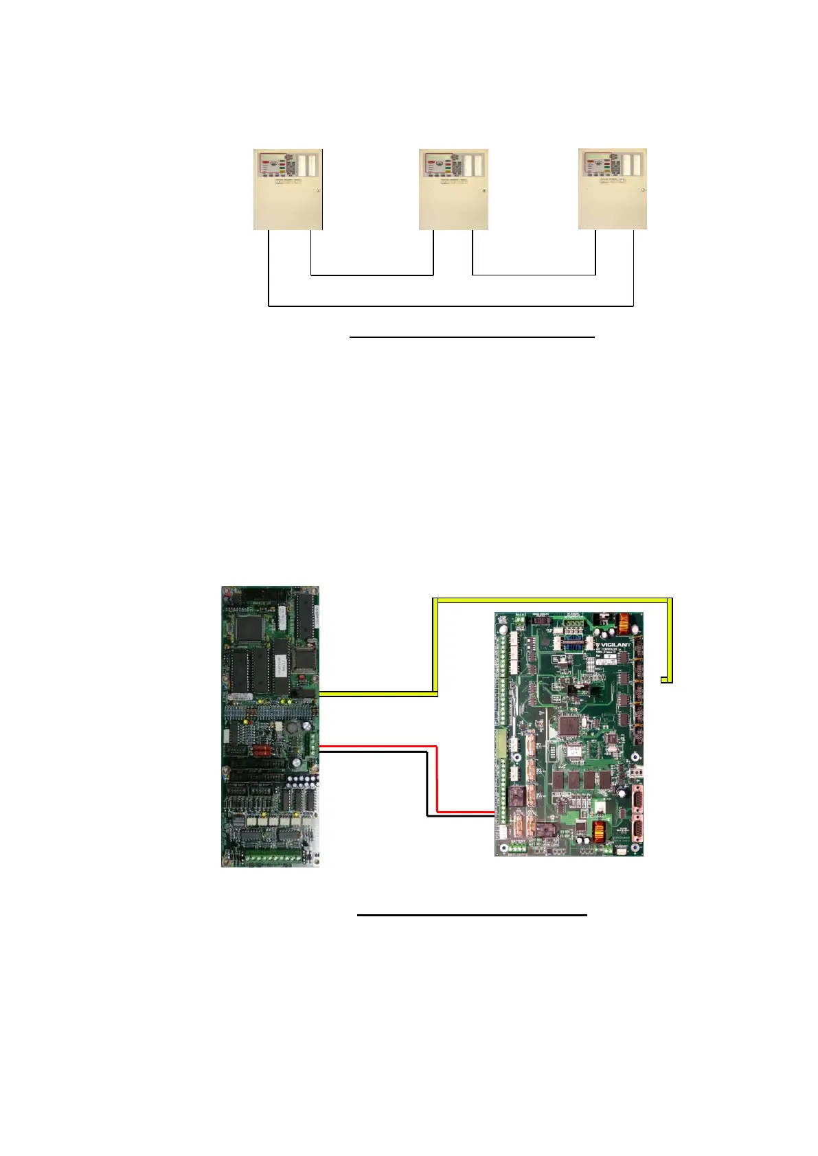
The I-HUB is powered by one of the MX1’s +VBF supplies. This supply
must not be used for any directly-connected field wiring, to ensure that
fuse failure caused by an external wiring fault does not disable the
network. Alternatively, the I-HUB (and fibre modems if included) could be
powered off the Loop Interface Supply terminals J33 using a fused power
lead (e.g., a spare LM0459 supplied with an MX Loop Card). The I HUB’s
J4 TTL serial port is connected using loom LM0152 to whichever serial
port (0, 2, 3 or 4) is configured in the MX1 for networking as shown in
Figure 11-22.
Figure 11-22 – I-HUB to MX1 Wiring