Vigilant MX1-Au Operator Manual Document: LT0439
Page 23 October 2018 Issue 1.73
For detailed information on mounting, wiring and programming the PIB,
Moxa switch and Ethernet Extender please refer to: PIB User Manual
(LT0519).
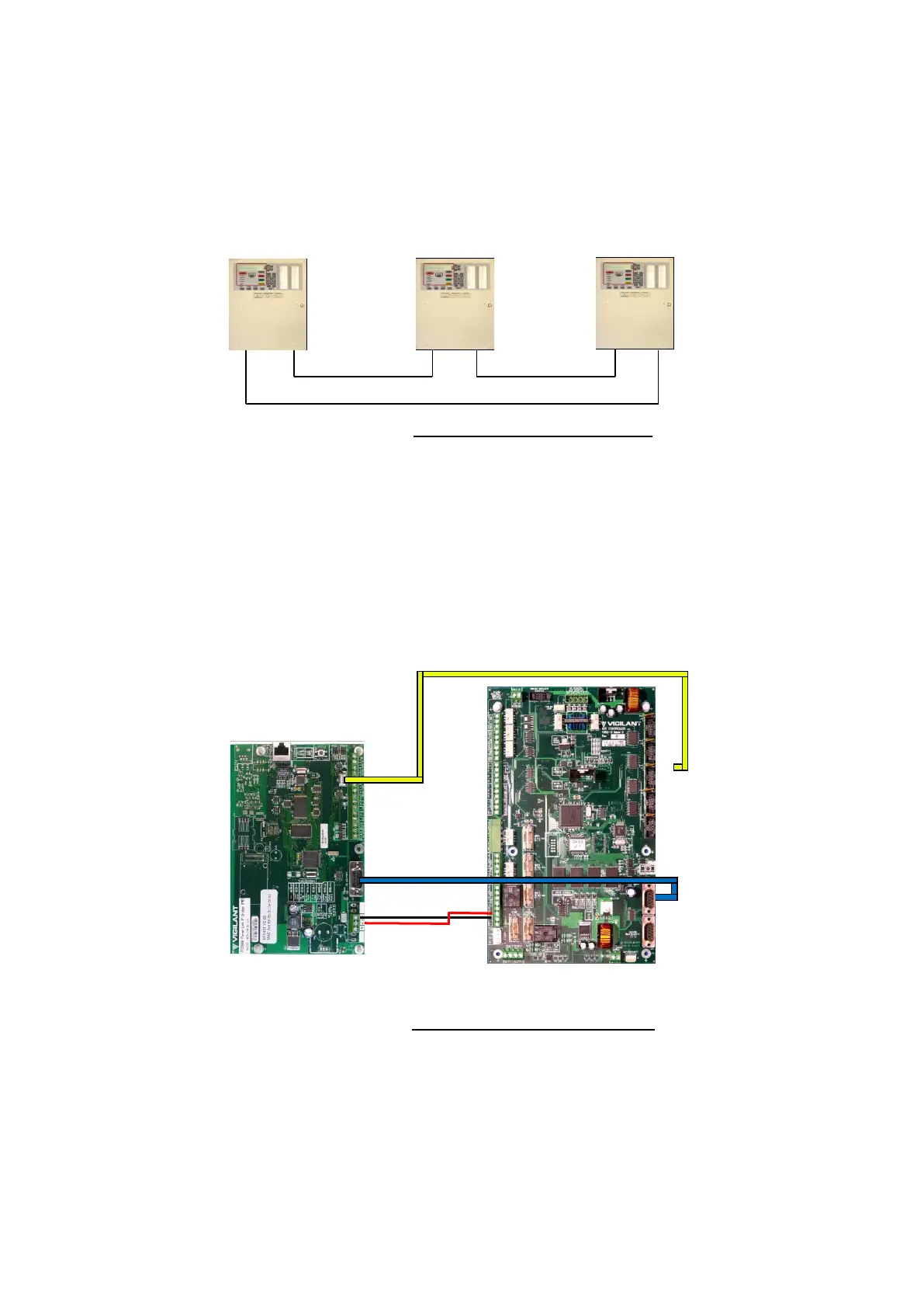
The PIB comes pre-configured for the recommended “RING”
configuration using Moxa fibre switches as shown in Figure 11-26.
Figure 11-26 – PIB Ring Network
The PIB and other network equipment is powered by the MX1 via one of
the MX1’s +VBF supplies. This supply must not be used for any directly-
connected field wiring. Alternatively, the PIB, Moxa switch, and Ethernet
Extender (if present) can be powered off the LOOP INTERFACE supply
terminals J33, using a fused lead (e.g., a spare LM0459 supplied with an
MX Loop Card). The PIB’s J24 serial port is connected using loom
LM0576 to whichever serial port (0, 2, 3 or 4) is configured in the MX1 for
networking.
Figure 11-27 – PIB to MX1 Wiring
To enable the PIB to be used to remotely access the MX1 for
programming, remote diagnostics or remote operation, then a null
modem serial cable LM0076 must be fitted between the PIB’s RS232
Port J22 and the MX1’s Diag/Prog port J22 as shown in Figure 11-27.
The PIB is connected to the Moxa Fibre/Ethernet switch as shown in
Figure 11-28.