VIKING TECHNICAL SUPPORT 1.800.908.0884
11
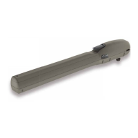
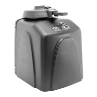
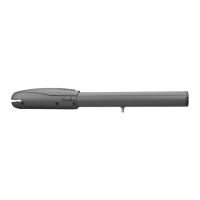
Release Handle
Release Key
Manual Release
When manual operation is required:
1.
Lift the Release Handle.
2.
Insert the Release Key and rotate Key to
unlock the Handle .
3.
Rotate Handle counter clockwise.
The gate can now be moved manually.
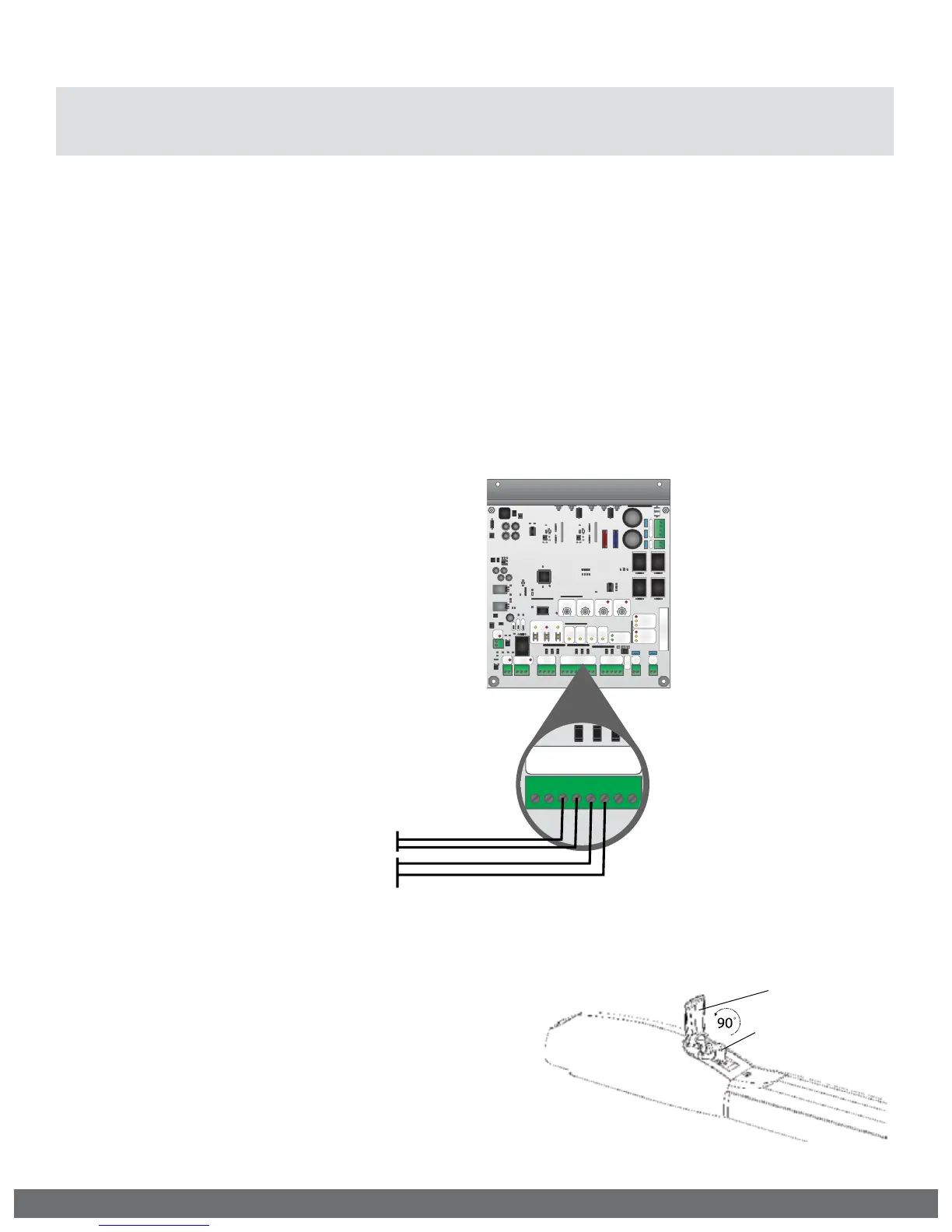
STEP 2
Connect the monitored entrapment protection
sensor(s) to the Viking control board as
illustrated below.
STEP 3
Learn the number of sensors connected:
•
Press and hold the Stop Button.
•
Connect the Power Harness to the Board.
•
Release the Stop Button after 10 seconds when
the “Center Loop” and “Radio Rec.” LEDs begin
to flash.
Aux.
Pwr
+
-
Magnetic Lock
N.O.
N.C.
COM
Guard Station
GND
Close
Stop
Open
Loop Connector
GND
Center
GND
ReOpen
GND
UL
GND
+28V
Radio Station
GND
GND
Radio
+28V
+28V
Class 2
Supply +28V
Master
Slave
Siren
+
Limit Close
Limit Open
Slave
Limit Close
Limit Open
Master
Low Bat
Power
Radio
Rec.
UL
Sens
ReOpen
Sens
Center
Loop
OpenStopClose
Speed Overlap ODS
Timer
Sync
Auto Open
AC
AC
+
-
+
-
Bat
DC IN
Max Min
Normal
60
3
100 0 60
Off
4A
15A
4
15
Aux.
Pwr
+
-
Magnetic Lock
N.O.
N.C.
COM
Guard Station
GND
Close
Stop
Open
Loop Connector
GND
Center
GND
ReOpen
GND
UL
GND
+28V
Radio Station
GND
GND
Radio
+28V
+28V
Class 2
Supply +28V
Master
Slave
Siren
+
Limit Close
Limit Open
Slave
Limit Close
Limit Open
Master
Low Bat
Power
Radio
Rec.
UL
Sens
ReOpen
Sens
Center
Loop
OpenStopClose
Speed Overlap ODS
Timer
Sync
Auto Open
Dual Gate
MS
AC
AC
+
-
+
-
Bat
DC IN
Max Min
Normal
60
3
100 060
Off
4A
15A
4
15
Loop Connector
GND
Center
GND
ReOpen
GND
UL
GND
+28V
Loop Connector
GND
Center
GND
ReOpen
GND
UL
GND
+28V
10K (Sensor’s Monitored Terminals)
10K (Sensor’s Monitored Terminals)
STEP 1
Remove the Power Harness from the Control
Board.
NOTE: The “Stop” LED
will be flashing if there
is a failure with at
least one monitored
entrapment sensor
and the gate operator
will be rendered
inoperable.
“UL” Protects against entrapment in both the opening and closing directions. Input will
either stop the gate or reverse the gate approximately 12” in the opposite direction it was
traveling.
“ReOpen” Protects against entrapment in the closing direction ONLY. Input will reverse the
gate all the way to the Open Limit.
IMPORTANT SAFETY INFORMATION
! WARNING! Not Following these instructions may cause severe injury or death.
! Cable use in Class 2 circuit to an external device shall be type CL2, CL2P, CL2R, CL2X or other
cable with equivalent or better electrical, mechanical, and ammability ratings.
Monitored Entrapment Protection Installation
!
IMPORTANT: A minimum of one Monitored External Entrapment Sensor is required to be
connected to the UL terminal OR the ReOpen terminal. If there is a possible entrapment
zone in the open direction, an external sensor MUST be wired to the “UL” input or the
installation will not comply with UL 325.