VIKING TECHNICAL SUPPORT 1.800.908.0884
20
High Voltage Supply Option
ELECTRICAL INSTALLATION
STEP 1
!
WARNING: SINGLE PHASE AC ONLY
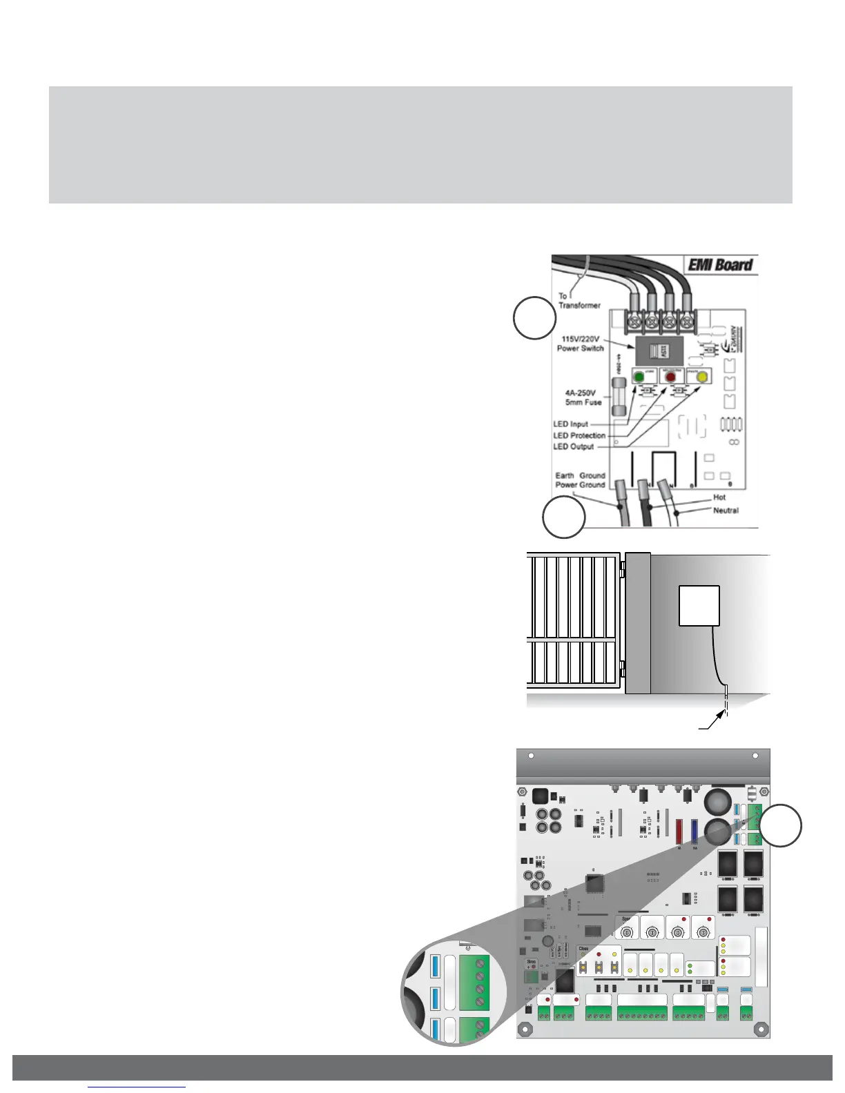
At the “EMI Board”:
a.
Set the “Voltage Selector” according
to the supply voltage (115V or 230V).
b.
Connect the incoming power wires
to the terminals as shown in the
illustration.
c.
Ground the ECU cabinet according to
local code or guidelines.
d.
Turn on the main facility breaker and
verify that all three (3) Status LEDs are
illuminated on the EMI Board.
Tips for proper ground installation:
To minimize the effects caused by lightning, follow
these guidelines:
•
Use a ground rod to provide a ground reference.
•
Consult your city code and be aware of
underground services in the site of the gate
operator to prevent inconveniences.
•
Always use a single bonding point for grounding.
•
All ground wires must be as short and as thick as
possible.
•
Prevent unnecessary turns or loops in all ground
wires.
STEP 2
At the Control Board:
a.
Reinstall the Control Board Mounting
Plate with the Control Board.
b.
Connect the outbound wires from the
Toroidal Transformer to the Green
and White “AC” wires of the “Power
Harness”. Polarity is not important.
Verify the “POWER” LED is illuminated
solid.
c.
Reconnect all other harnesses.
Ground Rod
Aux.
Pwr
+ -
Magnetic Lock
N.O.
N.C.
COM
Guard Station
GND
Close
Stop
Open
Loop Connector
GND
Center
GND
ReOpen
GND
UL
GND
+28V
Radio Station
GND
GND
Radio
+28V
+28V
Class 2
Supply +28V
Master
Slave
Siren
+
Limit Close
Limit Open
Slave
Limit Close
Limit Open
Master
Low Bat
Power
Radio
Rec.
UL
Sens
ReOpen
Sens
Center
Loop
OpenStopClose
SpeedOverlap ODS
Timer
Sync
Auto Open
AC
AC
+
-
+
-
Bat
DC IN
Max Min
Normal
60
3
100 0 60
Off
4A
15A
4
15
Aux.
Pwr
+ -
Magnetic Lock
N.O.
N.C.
COM
Guard Station
GND
Close
Stop
Open
Loop Connector
GND
Center
GND
ReOpen
GND
UL
GND
+28V
Radio Station
GND
GND
Radio
+28V
+28V
Class 2
Supply +28V
Master
Slave
Siren
+
Limit Close
Limit Open
Slave
Limit Close
Limit Open
Master
Low Bat
Power
Radio
Rec.
UL
Sens
ReOpen
Sens
Center
Loop
OpenStopClose
SpeedOverlap ODS
Timer
Sync
Auto Open
MS
AC
AC
+
-
+
-
Bat
DC IN
Max Min
Normal
60
3
100 060
Off
4A
15A
4
15
AC
AC
+
-
+
-
Bat
DC IN
AC
AC
+
-
+
-
Bat
DC IN
2b
! Caution: Always turn off power breakers when working with high voltage. DO NOT
connect the “Power Harness” to the Control Board until the electrical installation is
complete and ready for verification. To reduce the risk of electric shock, this equipment
(external plug-in transformer) has a grounding type Plug, that has a third (grounding) pin. This
plug will only t into a grounding type outlet. If the plug does not t into the outlet, contact a
qualied electrician to install the proper outlet. Do not change the plug in any way.
1b
1a