VIKING TECHNICAL SUPPORT 1.800.908.0884
22
Aux.
Pwr
+
-
Magnetic Lock
N.O.
N.C.
COM
Guard Station
GND
Close
Stop
Open
Loop Connector
GND
Center
GND
ReOpen
GND
UL
GND
+28V
Radio Station
GND
GND
Radio
+28V
+28V
Class 2
Supply +28V
Master
Slave
Siren
+
Limit Close
Limit Open
Slave
Limit Close
Limit Open
Master
Low Bat
Power
Radio
Rec.
UL
Sens
ReOpen
Sens
Center
Loop
OpenStopClose
Speed Overlap ODS
Timer
Sync
Auto Open
AC
AC
+
-
+
-
Bat
DC IN
Max Min
Normal
60
3
100 0 60
Off
4A
15A
4
15
Aux.
Pwr
+
-
Magnetic Lock
N.O.
N.C.
COM
Guard Station
GND
Close
Stop
Open
Loop Connector
GND
Center
GND
ReOpen
GND
UL
GND
+28V
Radio Station
GND
GND
Radio
+28V
+28V
Class 2
Supply +28V
Master
Slave
Siren
+
Limit Close
Limit Open
Slave
Limit Close
Limit Open
Master
Low Bat
Power
Radio
Rec.
UL
Sens
ReOpen
Sens
Center
Loop
OpenStopClose
Speed Overlap ODS
Timer
Sync
Auto Open
MS
AC
AC
+
-
+
-
Bat
DC IN
Max Min
Normal
60
3
100 060
Off
4A
15A
4
15
Class 2
Supply +28V
Master
Class 2
Supply +28V
Master
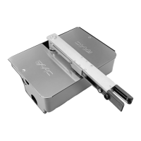
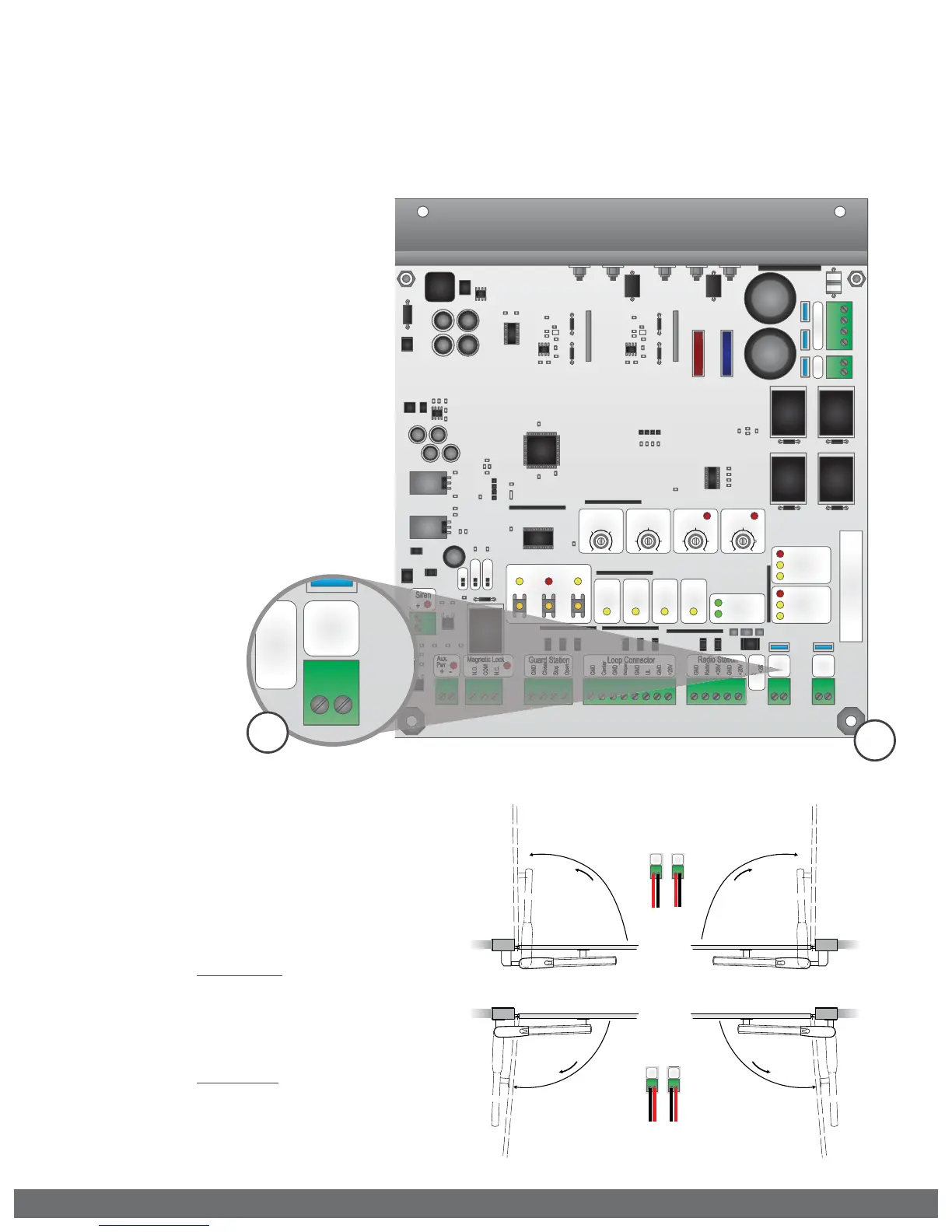
Motor Cable - Master (Single)
NOTE:
The position of the motor wires will dictate in which direction the motor will travel
when given an open or close command.
ELECTRICAL INSTALLATION
Motor Wires Polarity
Master Pull or Push to Open:
Connect the motor wires to the “Master”
Terminal Block according to the opening
direction.
STEP 3
Master Motor:
a.
Connect motor wires to the
“Master” Terminal Block, according
to the opening direction as
described below.
b.
Attach the grounding wire, non
insulated, to the Board Mounting
Plate using the screw provided.
PULL OPEN
BLACK RED
PUSH OPEN
RED BLACK
3a
Outside
Inside
OPEN RIGHT
Open
OPEN RIGHT
Open
OPEN LEFT
Open
OPEN LEFT
Open
Slave
Master
Slave
Master
RED
RED
BLACK
BLACK
BLACK
RED
BLACK
RED
3b