126
Intake and exhaust system
13
Install the exhaust elbow for the turbocharger (TC)
if required. Check that the mating surfaces on the
elbow and the turbocharger (TC) are clean. Install a
new gasket. Tighten the nuts to 22 Nm.
14
Connect the oil return line and the boost pressure
line to the turbocharger (TC).
15
Pour 100-140 ml of clean engine oil through the in-
take opening in the turbocharger central housing.
Turn the rotating unit by hand to distribute the oil to
the bearings.
16
Slide the hose on the intake manifold elbow onto the
compressor outlet and tighten the hose clamps.
17
Check that the passages in the air filter and hose
and in the intake cover and pipe are clean. Install
the air filter and intake cover and tighten the hose
clamps.
18
Place the supply line for the oil in position but do
not connect it. Operate the starter motor with the
stop button depressed or with the stop lever in the
STOP position until oil runs out of the supply line.
Ensure that the stop lever returns to the operating
position.
Connect the oil supply line.
Install the turbine backplate (heat shield) and its
spring clamps.
19
Start the engine and check that there are no oil or
air leaks (particularly at the line for the boost pres-
sure sensor which is installed between the com-
pressor housing and the control valve for the boost
pressure. The engine must be run at low speed for 3
or 4 minutes to start the oil circulating before the
engine speed is increased.
Boost pressure control valve,
checking
If the by-pass valve in the boost pressure control
valve does not open at the correct pressure, this
will affect the performance of the engine.
A low pressure setting can cause black exhaust
emissions at the marked engine speed and power
loss at 2,500 rpm.
A high pressure setting may cause excess pressure
in the cylinders, which may lead to damage to the
cylinder head gasket and to the bearings and pis-
tons.
The pressure setting can be checked as follows:
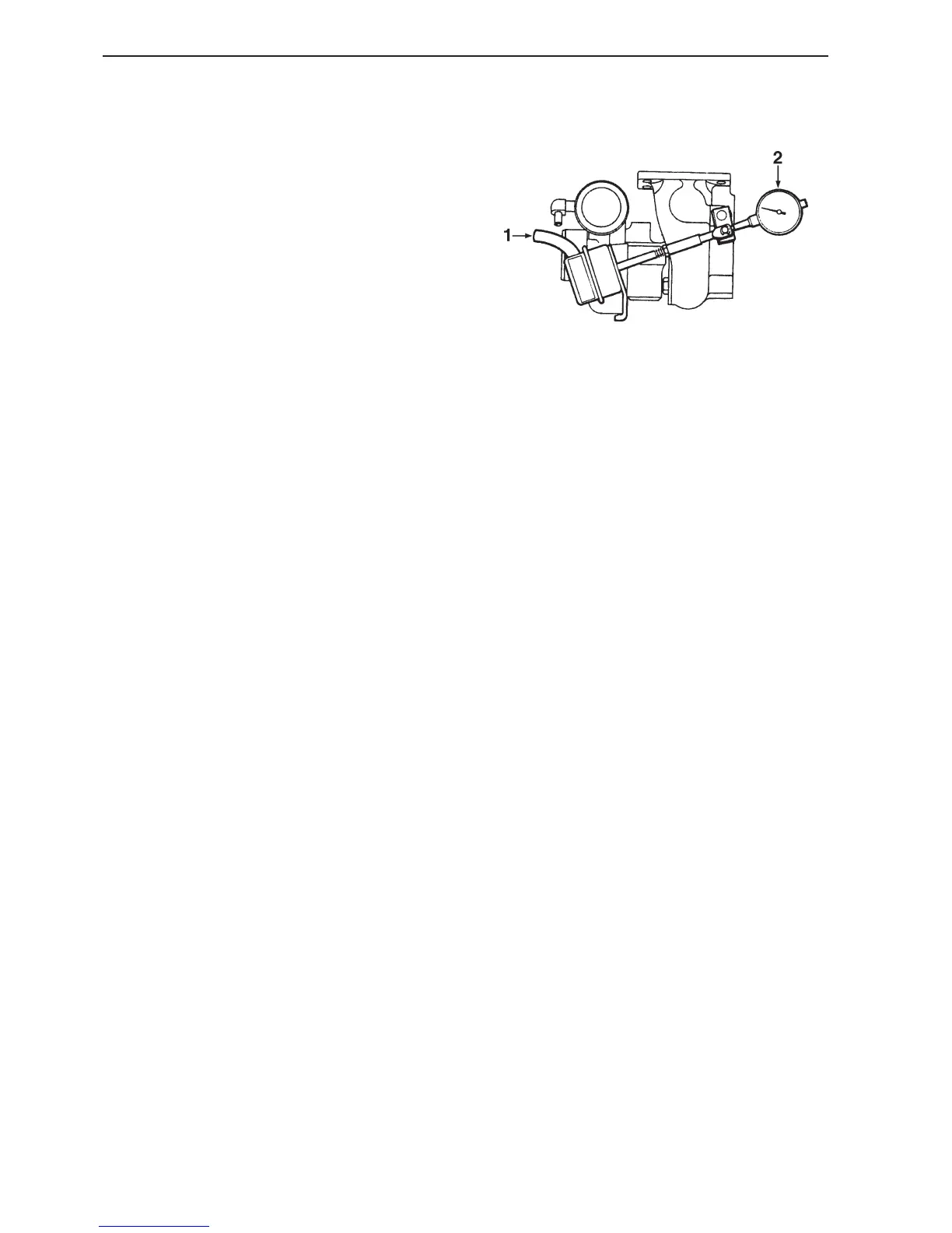
1
Disconnect the line for the boost pressure sensor
(1) and connect an air supply which can be regulat-
ed precisely and which is equipped with a precision
manometer. Position a dial indicator on the turbo-
charger (TC) with the measuring tip in contact with
the control rod to measure the axial movement of
the rod (2).
2
Check that the pressure required to move the rod
0.38 mm is within the range 89-97 kPa for the
TMD22 (the values for the TAMD22 are 1 mm and
135 kPa). Check that the dial indicator returns to
zero when the air pressure is released. Repeat the
test several times to ensure an accurate measure-
ment. It may be necessary to tap lightly on the tur-
bine housing with a soft-faced hammer during this
procedure.
3
If the function of the pressure control valve is
faulty, the turbo must be replaced. No adjustments
are permitted.
4
Remove the test equipment and connect the line to
the boost pressure sensor.