90
Fuel injection system
9
Check that the key is correctly installed on the
pump shaft. Install the fuel injection pump in posi-
tion with the locknuts sufficiently tightened to hold
the pump secure, but not so much that it prevents
radial movement in the housing. Install the screws
holding the support bracket against the rear end of
the pump and finger tighten them.
10
Install the pulley on the shaft with the key in the
correct keygroove, see operation 15A-05. Hold the
belt so that it does not move and install the pulley
nut and washer. Tighten the nut so that the pulley is
pressed up on the shaft, do not tighten the nut to
the final torque.
11
If the pump shaft is installed in top dead center po-
sition (see “Note!” above): Ensure that the tooth
with the correct marking turned towards the arrow
on the timing cover and install the timing belt, see
operation 15A-04. Check the position of the journals
in the cut out in the pump mounting flange. Check
that the fuel injection pump can be turned clockwise
seen from the rear when the belt tension is adjust-
ed. If there is not sufficient room for movement
change the position of the belt on the pulley. Adjust
the timing belt tension, operation 15A-03. Check
that the journals are not in the end of the groove in
the pump mounting flange and tighten the locknuts.
Unscrew the mounting screw on the side of the
pump and install the spacer under the screw.
Tighten the mounting screw to 12 Nm. Tighten the
nut for pump pulley to 60 Nm. Check the fuel injec-
tion pump adjustment, operations 17A-03.
If the pump shaft is not secure: Ensure that the
tooth with the correct marking turned towards the
arrow on the timing cover and install the adjustment
drifts through the smooth holes in the pump pulley.
Install the timing belt, see operation 15A-04 and re-
move the adjustment drifts. Adjust the belt tension,
operation 15A-03. Tighten the nut for pump pulley to
60 Nm. Adjust the pump setting, operation 17A-03
and tighten the pump flanged nuts.
12
Tighten the screws holding the support bracket at
the rear of the pump against the installation bracket.
13
Check that the adjustment drifts are removed.
14
Install the cap of the timing cover, operation 15A-
01.
15
Install the low pressure lines. Certain pumps have a
banjo screw, which is marked “OUT” and this must
be installed at the fuel return connection at the tank.
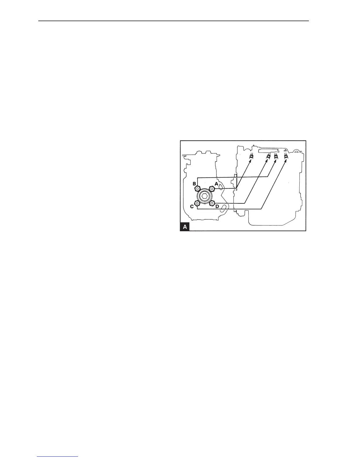
16
Install the delivery pipes to the pump. Use a wrench
to prevent the output terminals on the fuel pump
(FP) from moving when the delivery lines are in-
stalled. The connections to the pump are as dis-
played in illustration A. Do not tighten the connector
to the injectors until the system has been bled.
17
Connect the engine speed regulator to the fuel
pump (FP) and connect the stop control if required.
Connect the cables for the stop solenoid on the
pump. Connect the battery.
18
Bleed the fuel injection system, operation 19A-08.