Contents
Chapter 1 Introduction ...................................................................................... 1
1.0 Technical parameters......................................................................................... 1
1.1 Description of Name Plate ................................................................................ 4
1.2 Selection Guide - Performance tables ............................................................... 5
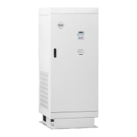
1.3 Drawing of external dimensions of the inverter - Dimension tables ................ 8
1.4 Inspection ........................................................................................................ 11
Chapter 2 Installation and wiring .................................................................... 12
2.1 Environment and installation requirements .................................................. 12
2.2 Installation space ............................................................................................ 13
2.3. Connection of inverter V 810 to power grid ................................................... 14
2.3.1 Connection the main power part of the inverter ......................................... 14
2.4 Terminal block configuration .......................................................................... 14
2.4.1 Main circuit terminal block ........................................................................... 14
2.4.2 NPN and PNP control circuit terminal block ................................................. 16
2.5 Wiring diagram of the V 810 inverter in the NPN mode ................................. 18
2.5.1 Wiring diagram of the V 810 inverter in PNP mode ..................................... 19
2.6 Main circuit connection ................................................................................... 20
2.6.1 Connection of the main circuit on the input side ......................................... 20
2.6.2 Main circuit connection on the inverter side ............................................... 21
2.6.3 Main circuit connection on the motor side .................................................. 21
2.6.4 Connection of the regeneration unit ............................................................ 22
2.6.5 Common DC bus connection ........................................................................ 22
2.6.6 Earth connection (PE) ................................................................................... 23
2.7 EMC compliant installation instructions ......................................................... 23
2.7.1 General EMC information ............................................................................. 24
2.7.2 EMC properties of the converter .................................................................. 24
2.7.3 EMC installation instructions ........................................................................ 24
Chapter 3 Operation ........................................................................................ 28
3.1 Description of the keyboard (control panel) ................................................... 28
3.2 The descriptions of the button’s function ...................................................... 28
3.3 The descriptions of the light indicator ............................................................ 29
3.4 Operation - parameter setting ........................................................................ 30
3.5 Running converter and PTC protection settings .............................................. 32