Chapter 2 Wiring of V 810
22
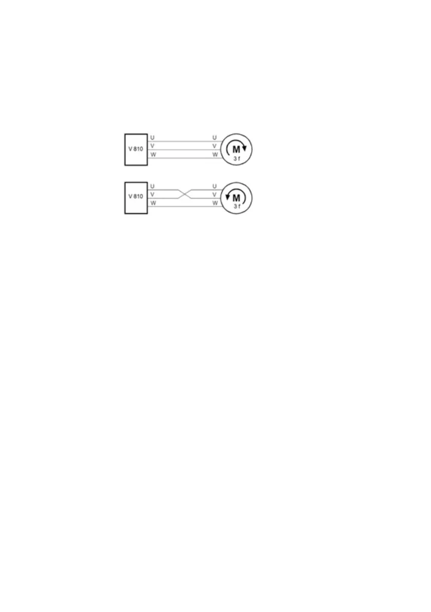
- Changing the direction of rotation of the electric motor shaft: the direction of rotation
can be changed by exchanging the two output lines at the output of the frequency
converter or at the terminal board of the electric motor.
The direction of rotation of the motor can be changed by swapping the two output lines
on the inverter or on the motor.
2.6.4 Connection of the regeneration unit
The regeneration unit is used to supply the electricity produced by braking the motor to
the grid. Compared to a traditional 3-phase inverse parallel bridge rectifier, the
regeneration unit uses IGBTs so that the total harmonic distortion (THD) is less than 4%.
The regeneration unit is often used in conjunction with centrifugal and lifting devices.
2.6.5 Common DC bus connection
The common DC bus method is widely used in the paper and fibber industries, which need
to coordinate multiple motors. In these applications, some motors are running, while
others are in regenerative braking (electricity generation). The regenerated energy is
automatically balanced via a common DC bus, which means that it can be supplied to the
motor in the running state. Therefore, the power consumption of the whole system will be
lower compared to the traditional method (one inverter drives one motor).
Let two motors run at the same time (eg winding / unwinding application), one is running
and the other is in regenerative mode. In this case, the DC buses of the two converters can
be connected in parallel so that the regenerated energy can be fed to the motor in the
running state whenever necessary. The detailed connection is shown in the following
figure ……
Note: When connected to a common DC bus, both inverters must be the same. Make sure
they are turned on at the same time.