116 • I/O Modules
WAGO-I/O-SYSTEM 750
DeviceNet
750-638, 753-638
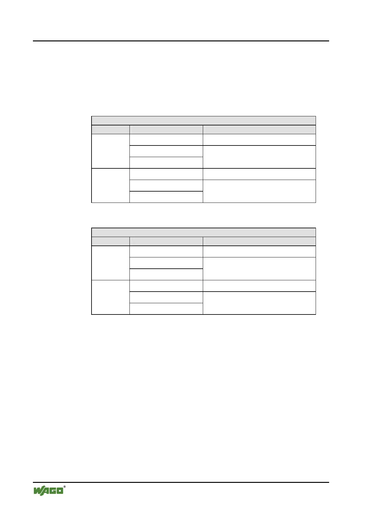
The above Counter Modules have a total of 6 bytes of user data in both the In-
put and Output Process Image (4 bytes of counter data and 2 bytes of con-
trol/status). The two counter values are supplied as 16 bits. The following ta-
bles illustrate the Input and Output Process Image, which has a total of 6 bytes
mapped into each image.
Input Process Image
Instance Byte Destination Remark
S0 Status byte of Counter 1
D0
n
D1
Counter Value of Counter 1
S1 Status byte of Counter 2
D2
n+1
D3
Counter Value of Counter 2
The specialty modules represent 2x3 bytes input data and seize 2 Instances in
Class (0x67).
Output Process Image
Instance Byte Destination Remark
C0 Control byte of Counter 1
D0
n
D1
Counter Setting Value of Counter 1
S1 Control byte of Counter 2
D2
n+1
D3
Counter Setting Value of Counter 2
And the specialty modules represent 2x3 bytes output data and seize 2 In-
stances in Class (0x68).
Pulse Width Modules
750-511, (and all variations)
The above Pulse Width modules have a total of 6 bytes of user data in both the
Input and Output Process Image (4 bytes of channel data and 2 bytes of con-
trol/status). The two channel values are supplied as 16 bits. Each channel has
its own control/status byte. The following table illustrates the Input and Output
Process Image, which has a total of 6 bytes mapped into each image.
 Loading...


