72 • DeviceNet
Network Architecture
WAGO-I/O-SYSTEM 750
DeviceNet
4.2.3 Network Topology
To build a simple DeviceNet network, you need a scanner (PC with a De-
viceNet fieldbus PCB card), a connection cable and a DC 24 V power pack to
ensure the power supply in addition to a DeviceNet fieldbus node.
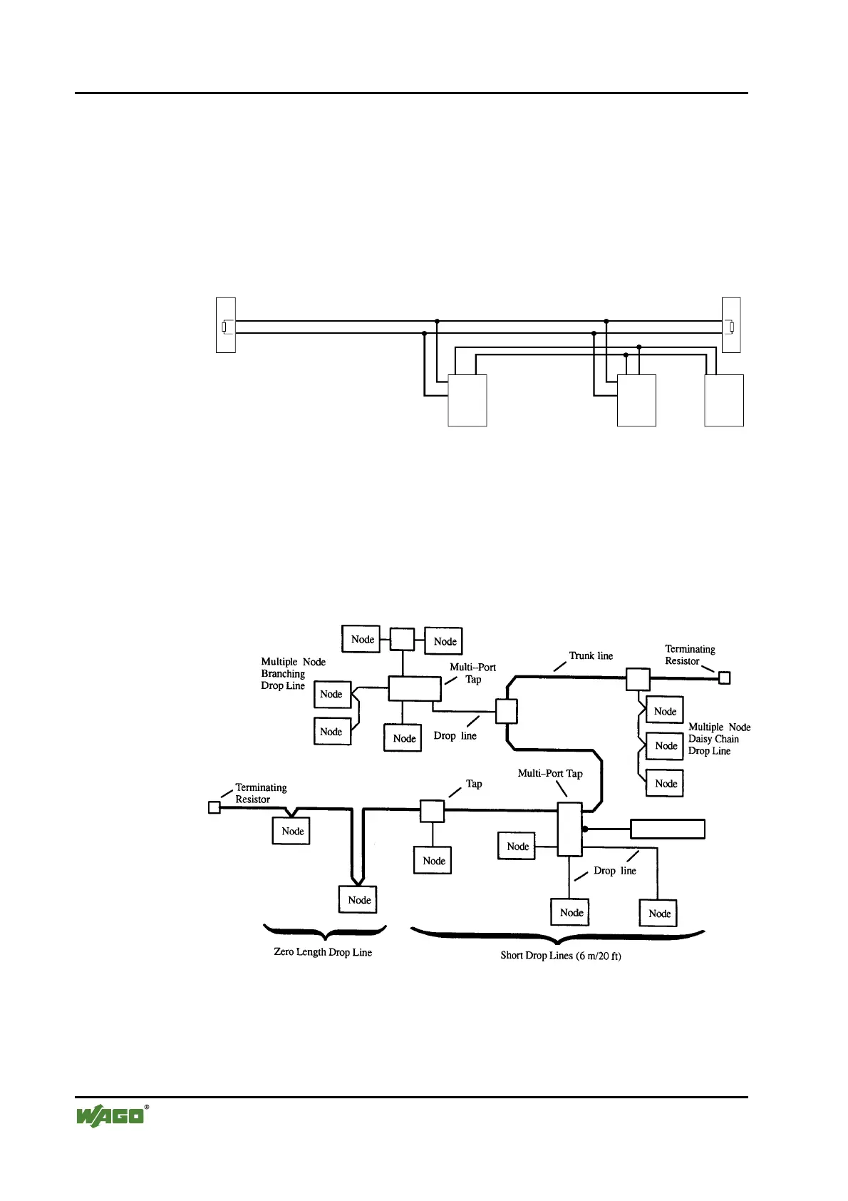
The CANopen network is constructed as a line structure with matching resis-
tors (120 Ohm).
WAGO
I/O
Sca nn er
Busn etz-
teil
Termination
120
Termination
120
In systems accommodating more than two stations, all subscribers are wired in
parallel. Node connection to the remote bus cable (trunk line) is made by
means of drop lines. For this purpose, the bus cable has to be looped without
interruption. A maximum length of 6 m for a drop line should not be ex-
ceeded.
The following is a topology example:
Power Supply
 Loading...


