I/O Modules • 107
WAGO-I/O-SYSTEM 750
DeviceNet
4 Channel Digital Input Modules
750-402, -403, -408, -409, -414, -415, -422, -423, -428, -432, -433,
753-402, -403, -408, -409, -415, -422, -423, -428, -432, -433, -440
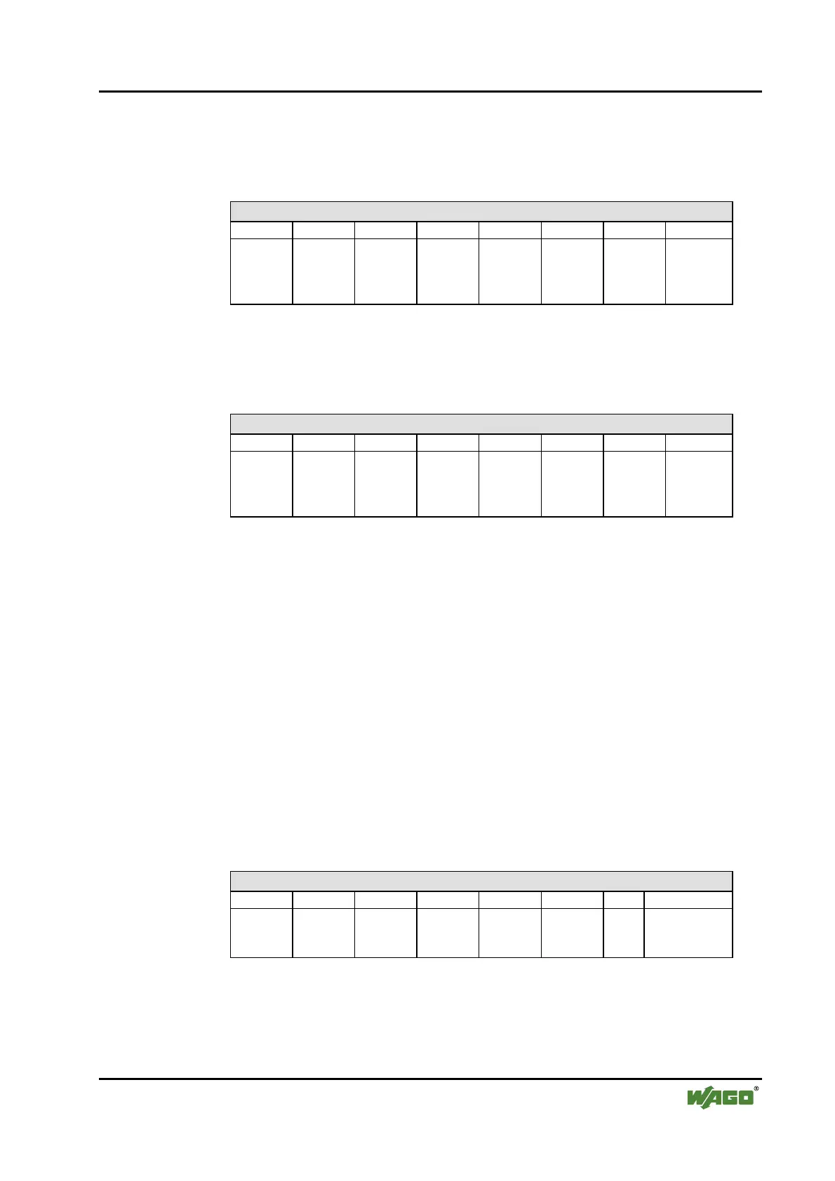
Input Process Image
Bit 7 Bit 6 Bit 5 Bit 4 Bit 3 Bit 2 Bit 1 Bit 0
Data bit
DI 4
Channel
4
Data bit
DI 3
Channel
3
Data bit
DI 2
Channel
2
Data bit
DI 1
Channel
1
The input modules seize 4 Instances in Class (0x65).
8 Channel Digital Input Modules
750-430, -431, -436, -437, 753-430, -431, -434
Input Process Image
Bit 7 Bit 6 Bit 5 Bit 4 Bit 3 Bit 2 Bit 1 Bit 0
Data bit
DI 8
Channel
8
Data bit
DI 7
Channel
7
Data bit
DI 6
Channel
6
Data bit
DI 5
Channel
5
Data bit
DI 4
Channel
4
Data bit
DI 3
Channel
3
Data bit
DI 2
Channel
2
Data bit
DI 1
Channel
1
The input modules seize 8 Instances in Class (0x65).
5.2.2 Digital Output Modules
Digital output modules use one bit of data per channel to control the output of
the corresponding channel. These bits are mapped into the Output Process Im-
age.
When analog output modules are also present in the node, the digital image
data is always appended after the analog data in the Output Process Image,
grouped into bytes.
Each output channel seizes one Instance in the Discrete Output Point Object
(Class 0x66).
1 Channel Digital Output Module with Input Process Data
750-523
Input Process Image
Bit 7 Bit 6 Bit 5 Bit 4 Bit 3 Bit 2 Bit 1 Bit 0
not
used
Status bit
„Manual
Operation“
The output modules seize 2 Instances in Class (0x65).
 Loading...


