70 • DeviceNet
Network Architecture
WAGO-I/O-SYSTEM 750
DeviceNet
Note
If possible, route the data line separately from all high current carrying ca-
bles.
Further information
For a detailed specification regarding the cable types, please refer to the
INTERNET under: http://www.odva.org.
4.2.1.3 Maximum Bus Length
In the following table, the permitted cable length is represented in dependence of the Baud
rate. Here, a differentiation is made between the maximum length for a transmission using a
thick and a thin cable.
Bus length Tap line length Baud rate
Thick + Thin Cable only
Thick
Cable
only
Thin
Cable
maximal cumulated
500 kbit/s
L
Tick
+ L
Thin
≤ 100 m (328 ft)
100 m
(328 ft)
100 m
(328 ft)
6 m (19,6 ft) 39 m (127,9 ft)
250 kbit/s
L
Tick
+ 2,5 • L
Thin
≤ 250 m (820,2 ft)
250 m
(820,2 ft)
100 m
(328 ft)
6 m (19,6 ft) 78 m (255,9 ft)
125 kbit/s
L
Tick
+ 5 • L
Thin
≤ 500 m (1640,4 ft)
500 m
(1640,4 ft)
100 m
(328 ft)
6 m (19,6 ft) 156 m (511,8 ft)
Tab. 4-1: Maximum bus length dependent on the set Baud rate
When specifying the maximum cable lengths, it is made sure that communica-
tion is possible between two nodes located at maximum distance to each other
(worst case).
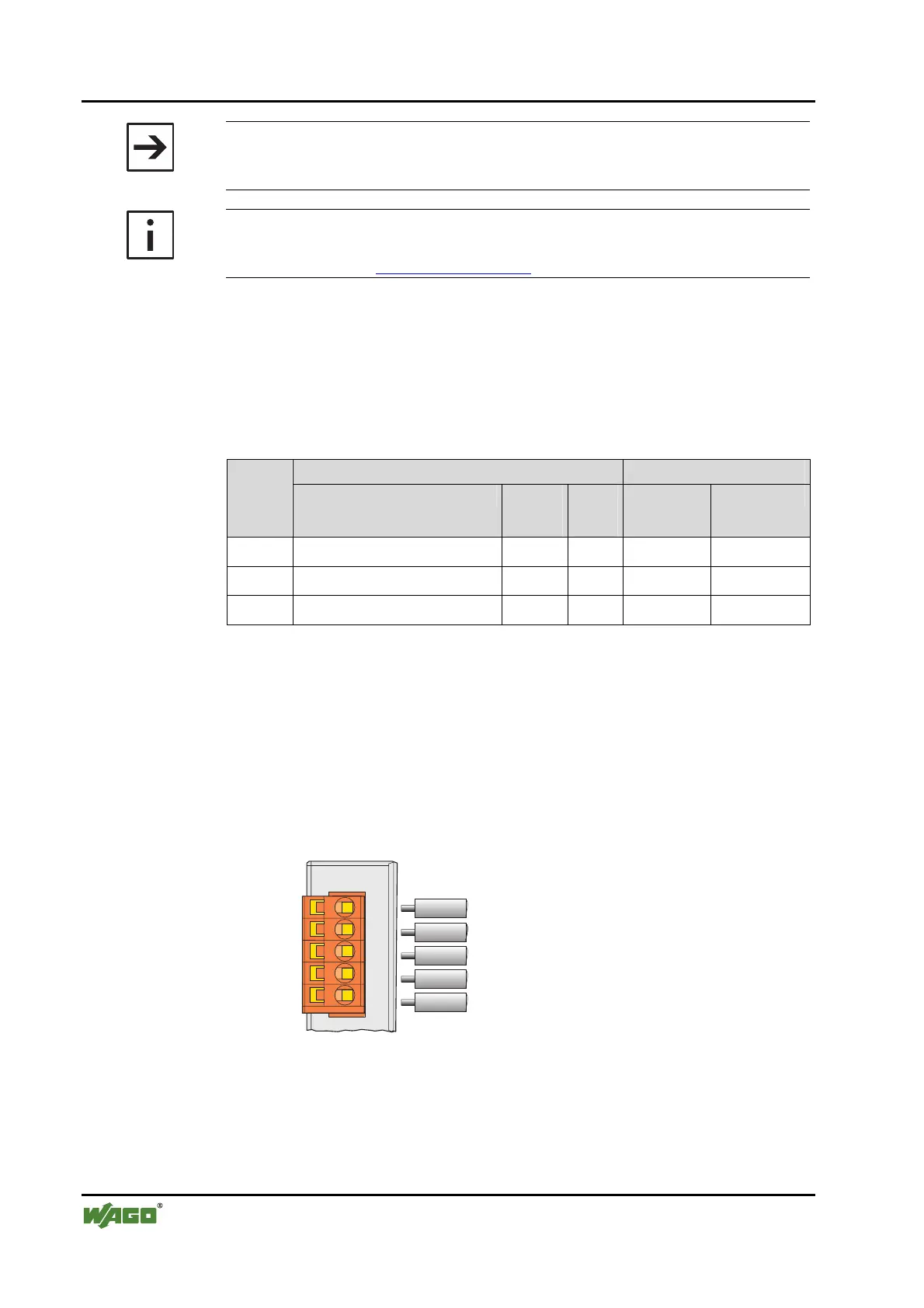
4.2.2 Cabling
The connection of a WAGO fieldbus node to the DeviceNet bus cable is made
by the supplied 5-pole plug (Multi Connector 231).
Fieldbus
connection
Series 231
(MCS)
CAN_High
drain
CAN_Low
V-
V+
Fig. 4-1: Plug assignment for the fieldbus connection
For wiring using a screened cable, the plus is assigned the connections V+, V-
for the voltage supply and with CAN_High, CAN_Low for data transmission.
The 24 V field bus supply is fed by an external fieldbus network power sup-
ply.
 Loading...


