The WAGO-I/O-SYSTEM 750 • 31
Power Supply
WAGO-I/O-SYSTEM 750
DeviceNet
By inserting an additional power supply module, the field supply via the
power contacts is disrupted. From there a new power supply occurs which
may also contain a new voltage potential.
Attention
Some bus modules have no or very few power contacts (depending on the I/O
function). Due to this, the passing through of the relevant potential is dis-
rupted. If a field supply is required for subsequent bus modules, then a power
supply module must be used.
Note the data sheets of the bus modules.
In the case of a node setup with different potentials, e.g. the alteration from
DC 24 V to AC 230V, a spacer module should be used. The optical separa-
tion of the potentials acts as a warning to heed caution in the case of wiring
and maintenance works. Thus, the results of wiring errors can be prevented.
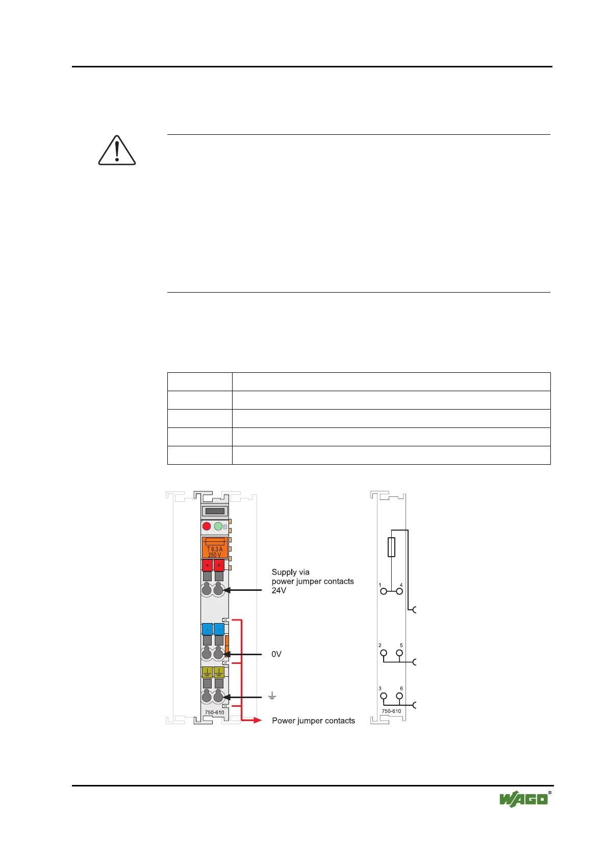
2.7.3.2 Fusing
Internal fusing of the field supply is possible for various field voltages via an
appropriate power supply module.
750-601 24 V DC, Supply / Fuse
750-609 230 V AC, Supply / Fuse
750-615 120 V AC, Supply / Fuse
750-610 24 V DC, Supply / Fuse / Diagnosis
750-611 230 V AC, Supply / Fuse / Diagnosis
Fig. 2-14: Supply module with fuse carrier (Example 750-610) g0xxx09e
 Loading...


