30 • The WAGO-I/O-SYSTEM 750
Power Supply
WAGO-I/O-SYSTEM 750
DeviceNet
2.7.3 Field Supply
2.7.3.1 Connection
Sensors and actuators can be directly connected to the relevant channel of the
bus module in 1-/4 conductor connection technology. The bus module supplies
power to the sensors and actuators. The input and output drivers of some bus
modules require the field side supply voltage.
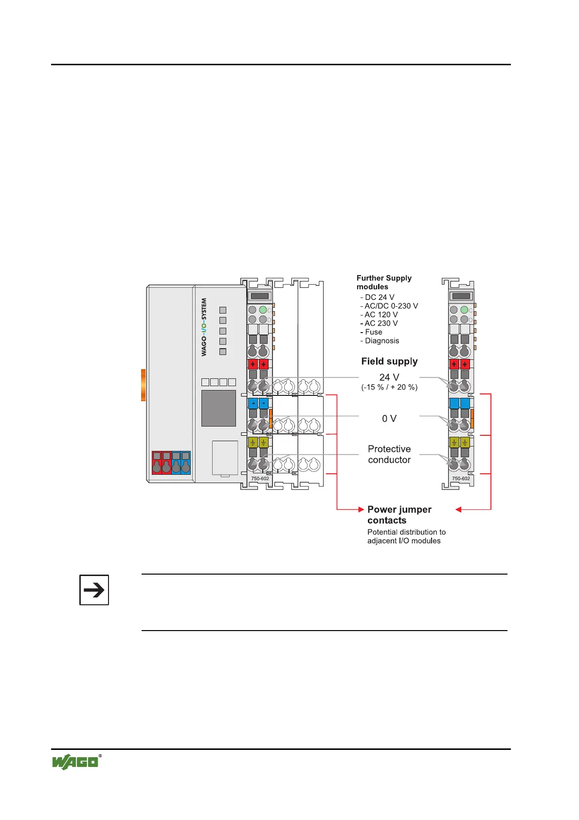
The power supply modules provide field side power (DC 24V). In this case it
is a passive power supply without protection equipment. Power supply mod-
ules are available for different potentials, e.g. DC 24 V, AC 230 V or others.
Likewise, with the aid of the power supply modules, various potentials can be
set up. The connections are linked in pairs with a power contact.
Fig. 2-13: Field Supply (Sensor / Actuator) g0xxx17e
Note
The 24 V field supply can be connected also directly to a bus module, if the
connection points are not needed for the peripheral device supply. In this
case, the connection points need the connection to the power jumper contacts
.
The supply voltage for the field side is automatically passed to the next mod-
ule via the power jumper contacts when assembling the bus modules .
The current load of the power contacts must not exceed 10 A on a continual
basis. The current load capacity between two connection terminals is identical
to the load capacity of the connection wires.
 Loading...


