24 • The WAGO-I/O-SYSTEM 750
Mechanical Setup
WAGO-I/O-SYSTEM 750
DeviceNet
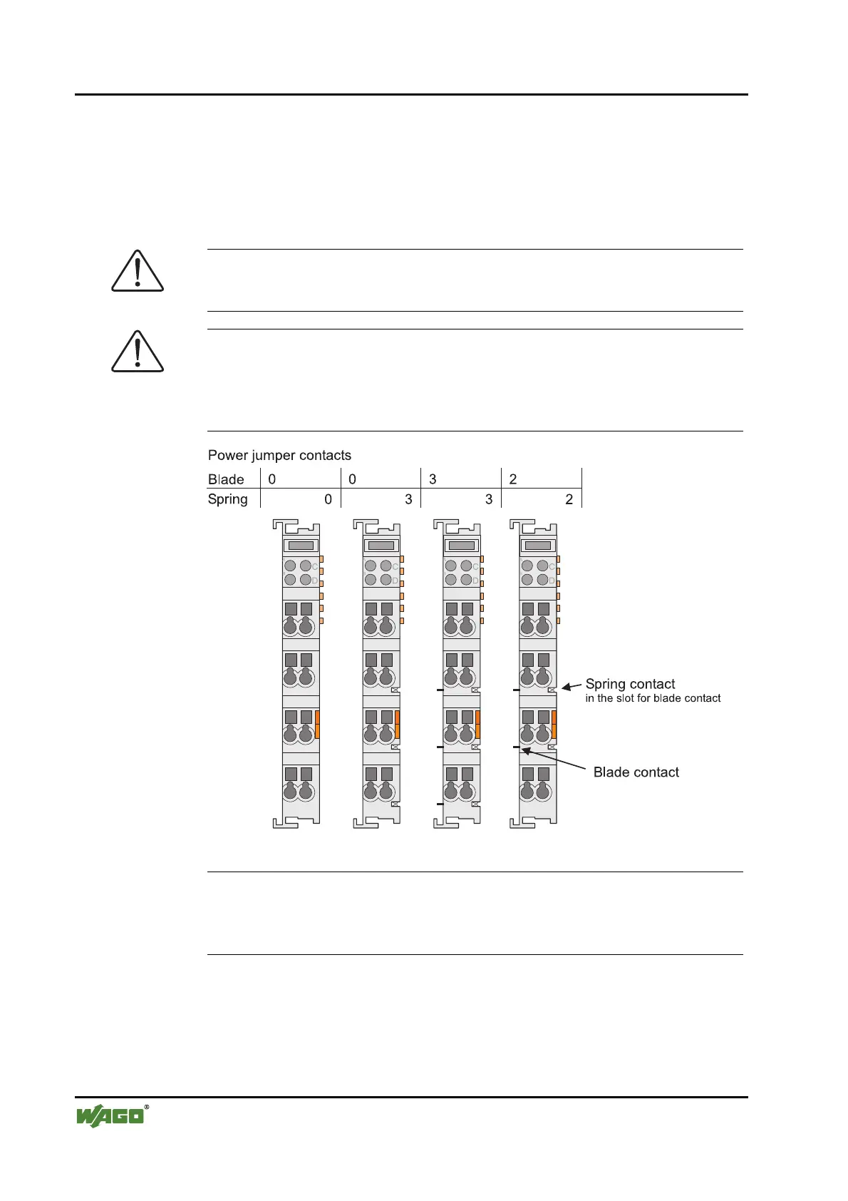
2.6.8 Power Contacts
Self-cleaning power contacts , are situated on the side of some components
which further conduct the supply voltage for the field side. These contacts
come as touchproof spring contacts on the right side of the bus modules. As
fitting counterparts the module has male contacts on the left side.
Danger
The power contacts are sharp-edged. Handle the module carefully to prevent
injury.
Attention
Please take into consideration that some bus modules have no or only a few
power jumper contacts. The design of some modules does not allow them to
be physically assembled in rows, as the grooves for the male contacts are
closed at the top.
Fig. 2-8: Example for the arrangement of power contacts g0xxx05e
Recommendation
With the WAGO ProServe® Software smartDESIGNER, the assembly of a
fieldbus node can be configured. The configuration can be tested via the inte-
grated accuracy check.
 Loading...


