I/O Modules • 113
WAGO-I/O-SYSTEM 750
DeviceNet
5.2.4 Analog Output Modules
The hardware of an analog output module has 16 bits of measured analog data
per channel and 8 bits of control/status. However, the DeviceNet cou-
pler/controller does not have access to the 8 control/status bits. Therefore, the
DeviceNet coupler/controller can only access the 16 bits of analog output data
per channel mapped in Intel format in the Output Process Image.
When digital output modules are also present in the node, the analog output
data is always mapped into the Output Process Image in front of the digital
data.
Each output channel seizes one Instance in the Analog Output Point Object
(Class 0x68).
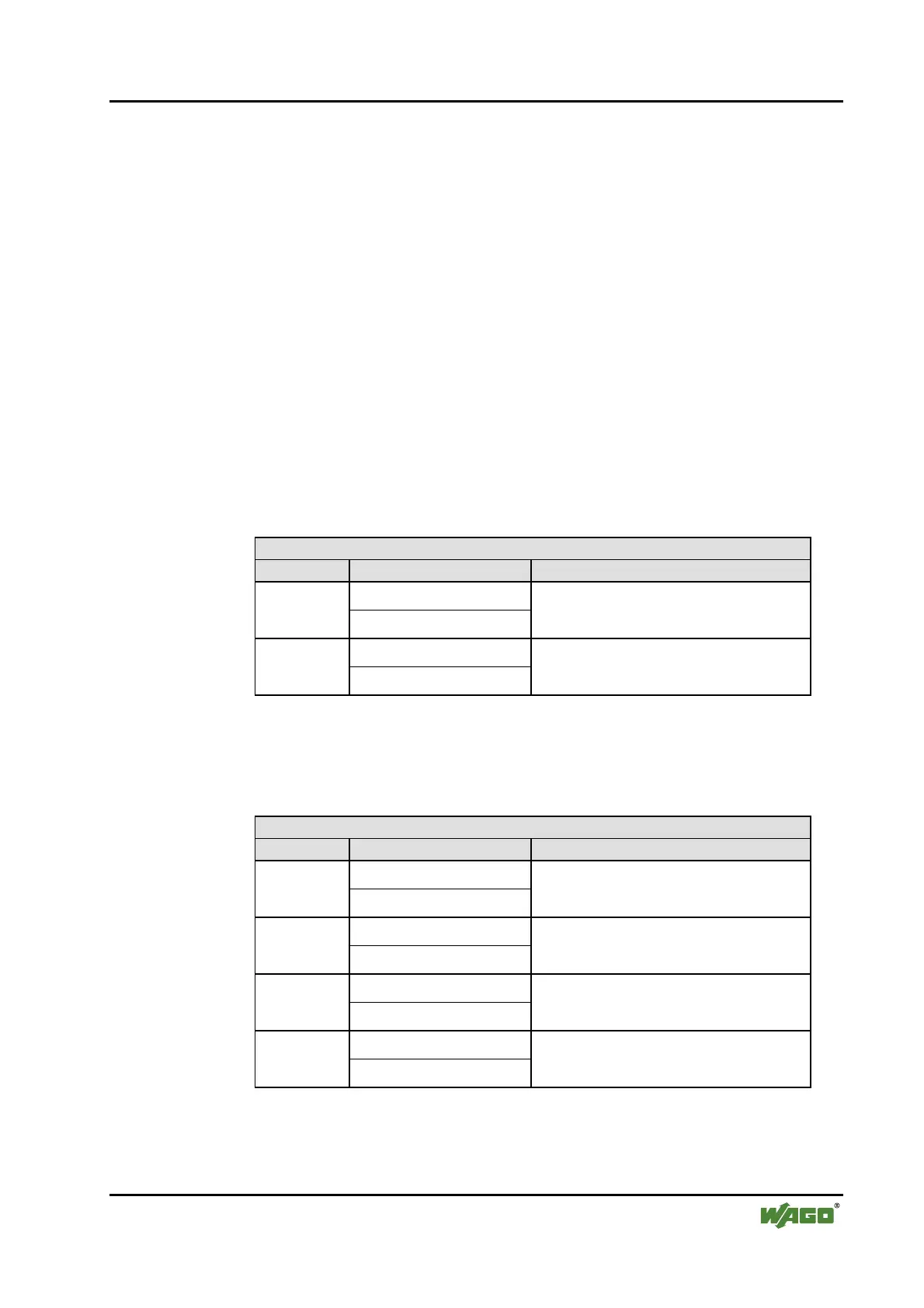
2 Channel Analog Output Modules
750-550, -552, -554, -556, -560, -585, (and all variations),
753-550, -552, -554, -556
Output Process Image
Instance Byte Destination Remark
D0
n
D1
Output Value Channel 1
D2
n+1
D3
Output Value Channel 2
The output modules represent 2x2 bytes and seize 2 Instances in Class (0x68).
4 Channel Analog Output Modules
750-553, -555, -557, -559, 753-553, -555, -557, -559
Output Process Image
Instance Byte Destination Remark
D0
n
D1
Output Value Channel 1
D2
n+1
D3
Output Value Channel 2
D4
n+2
D5
Output Value Channel 3
D6
n+3
D7
Output Value Channel 4
The output modules represent 4x2 bytes and seize 4 Instances in Class (0x68).
 Loading...


