60 • Fieldbus Coupler
Fieldbus Coupler 750-346
WAGO-I/O-SYSTEM 750
DeviceNet
3.1.8.1 Node status – Blink code from the 'I/O' LED
LED Color Meaning
IO red /green
/ orange
The 'I/O' LED indicates the node operation and signals faults occur-
ring.
The coupler starts up after switching on the supply voltage. The "I/O" LED
blinks. The "I/O" LED has a steady light following a fault free start-up.
In the case of a fault the "I/O" LED continues blinking. The fault is cyclically
displayed by the blink code.
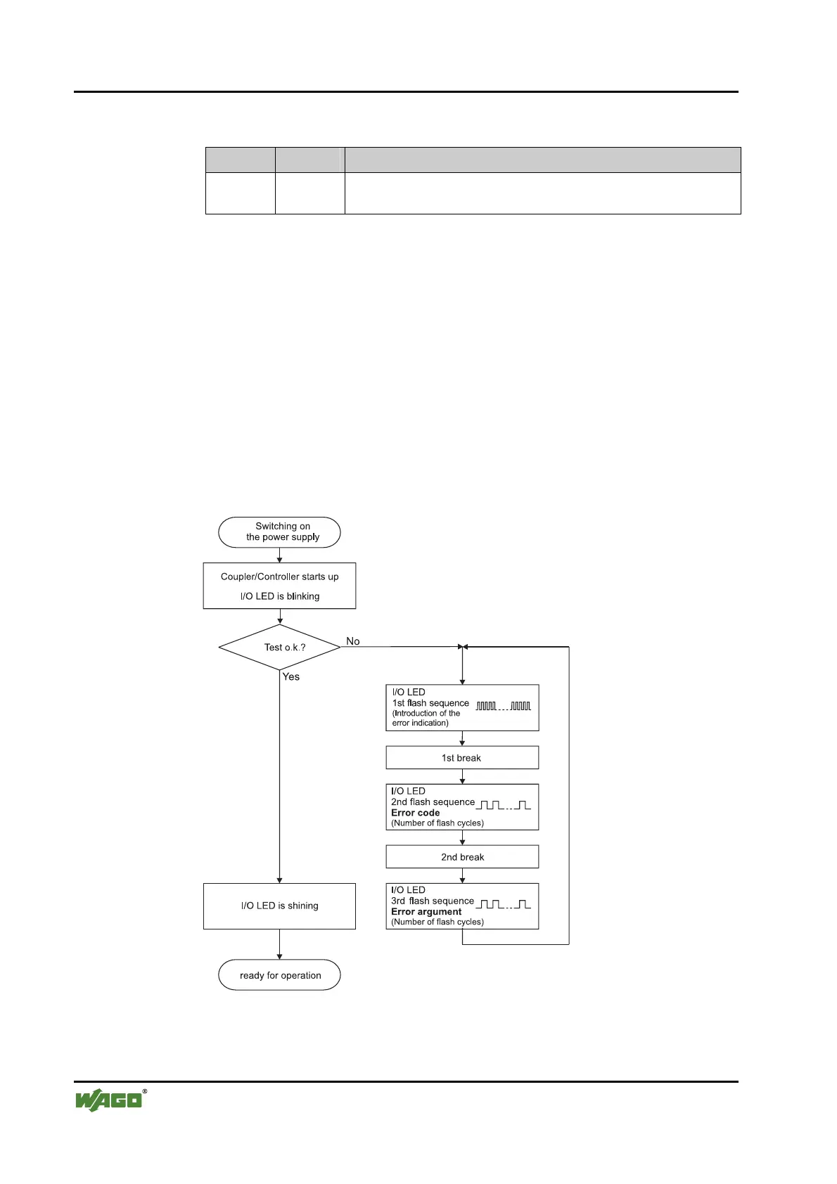
Detailed fault messages are displayed with the aid of a blink code. A fault is
cyclically displayed with up to 3 blink sequences.
• The first blink sequence (approx. 10 Hz) starts the fault display.
• The second blink sequence (approx. 1 Hz) following a pause. The
number of blink pulses indicates the fault code.
• The third blink sequence (approx. 1 Hz) follows after a further pause.
The number of blink pulses indicates the fault argument.
Fig. 3-19: Signalling the LED's node status g012111e
After overcoming a fault, restart the coupler by cycling the power.
 Loading...


