108 • I/O Modules
WAGO-I/O-SYSTEM 750
DeviceNet
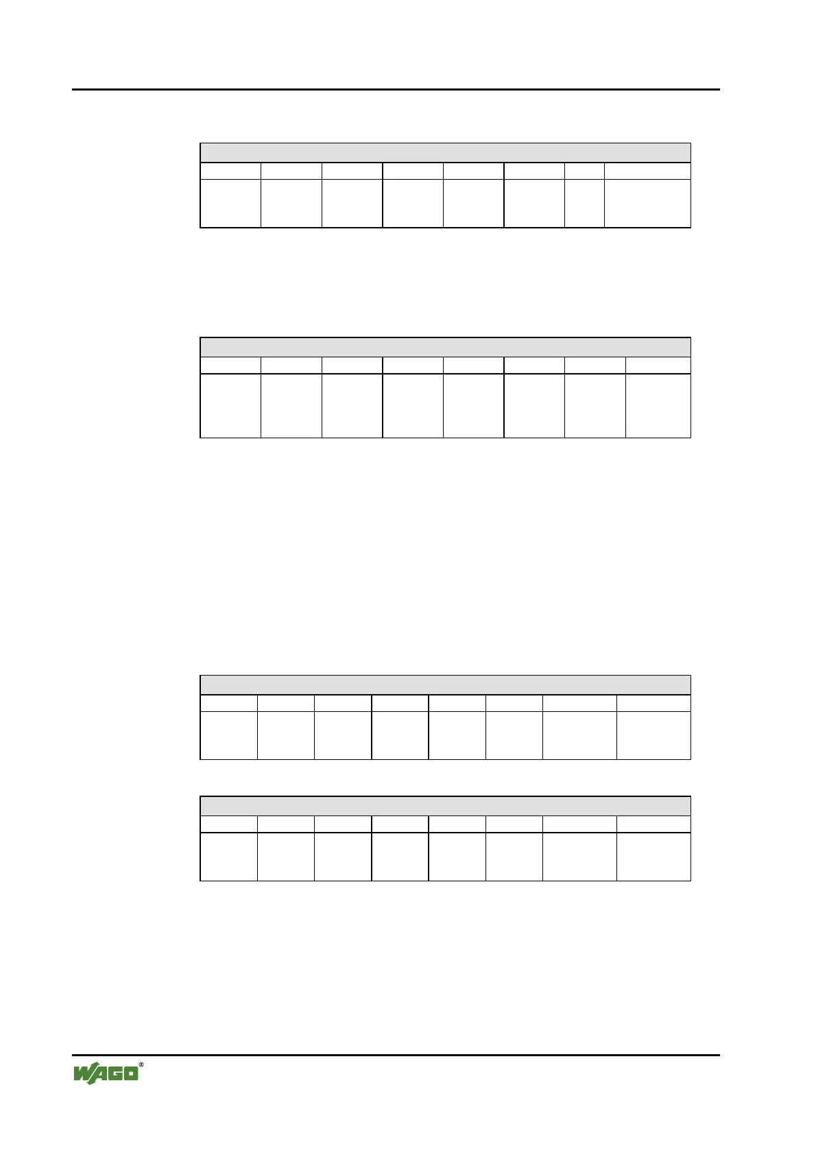
Output Process Image
Bit 7 Bit 6 Bit 5 Bit 4 Bit 3 Bit 2 Bit 1 Bit 0
not
used
controls
DO 1
Channel 1
And the output modules seize 2 Instances in Class (0x66).
2 Channel Digital Output Modules
750-501, -502, -509, -512, -513, -514, -517, -535, (and all variations),
753-501, -502, -509, -512, -513, -514, -517
Output Process Image
Bit 7 Bit 6 Bit 5 Bit 4 Bit 3 Bit 2 Bit 1 Bit 0
controls
DO 2
Channel
2
controls
DO 1
Channel
1
The output modules seize 2 Instances in Class (0x66).
2 Channel Digital Input Modules with Diagnostics and Input Process
Data
750-507 (-508), -522, 753-507
The 750-507 (-508), -522 and 753-507 digital output modules have a diagnos-
tic bit for each output channel. When an output fault condition occurs (i.e.,
overload, short circuit, or broken wire), a diagnostic bit is set. The diagnostic
data is mapped into the Input Process Image, while the output control bits are
in the Output Process Image.
Input Process Image
Bit 7 Bit 6 Bit 5 Bit 4 Bit 3 Bit 2 Bit 1 Bit 0
Diagnostic
bit S 2
Channel 2
Diagnostic
bit S 1
Channel 1
The output modules seize 2 Instances in Class (0x65).
Output Process Image
Bit 7 Bit 6 Bit 5 Bit 4 Bit 3 Bit 2 Bit 1 Bit 0
controls
DO 2
Channel 2
controls
DO 1
Channel 1
And the output modules seize 2 Instances in Class (0x66).
 Loading...


