2787-2146 (/0000-00x0)Properties
16 Product manual | Version: 1.2.2
Power Supply Pro 2
3.5.4 Signal
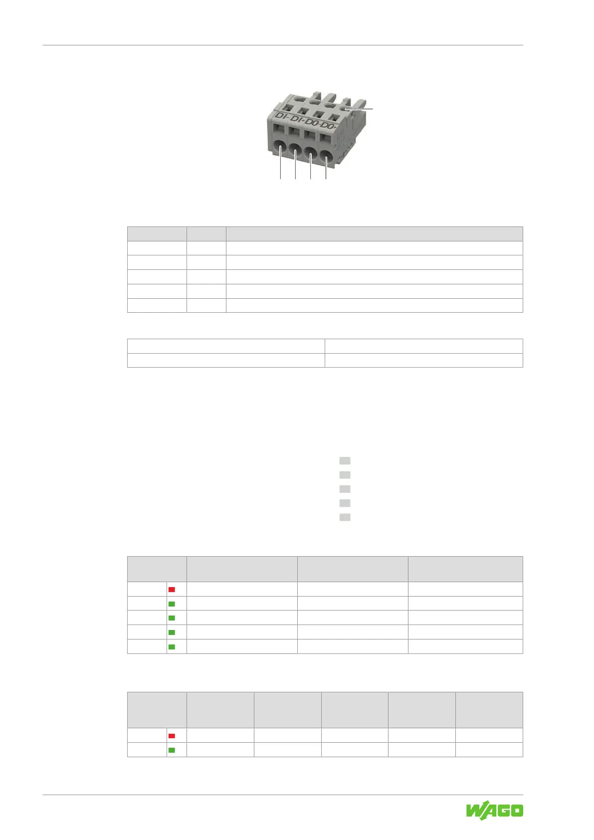
Figure6: Signal X3 Connection
Table11: Legend for Figure “Signal X3 Connection”
Position Pin Description
1 1 Contact “DI−” for input voltage
2 2 Contact “DI+” for input voltage
3 3 Contact “DO−” for output voltage
4 4 Contact “DO+” for output voltage
5 - Test slot
Table12: Details – Signal Connection
Series
721 Series (see section 8Accessories [}73])
Connection Technology CAGE CLAMP
®
3.6 Indicators
The product has an optical status indicator. This indicator consists of five LEDs.
These LEDs indicate operating states and Diagnostics.
> 100 %
> 75 %
> 50 %
> 25 %
DC OK
Figure7: Optical Status Indicator
Table13: Indication of Operating States – General
Indicator Product is in Standby Mode Latching Shutdown of Out-
put
1)
Boost Output (Signaled for
5s)
> 100% Off Flashing (0.5Hz) Flashing (2Hz)
> 75% Off Off Steady
> 50% Off Off Steady
> 25% Off Off Steady
DC OK Flashing (0.5Hz) Off Steady
1)
In the event of overload or overtemperature, or if electronic circuit breaker trips
Table14: Indication of Operating States – Output Power
Indicator DC OK / Output
Power <25%
Output Power
≥25% … <50%
Output Power
≥50% … <75%
Output Power
≥75% …
<100%
Output Power
≥100%
>100% Off Off Off Off Steady
>75% Off Off Off Steady Steady