2787-2146 (/0000-00x0) Installation and Removal
Product manual | Version: 1.2.2 31
Power Supply Pro 2
6Installation and Removal
NOTICE
Avoid electrostatic discharge!
The products are equipped with electronic components that you may destroy by electro-
static discharge when you touch. Please observe the safety precautions against electro-
static discharge in accordance with EN61340-5-1/-3. Pay attention while handling the
products to good grounding of the environment (persons, job and packing).
NOTICE
Do not cover the ventilation openings!
To ensure adequate air circulation, the ventilation openings must be kept clear. Maintain
a distance of at least 50mm from the ventilation openings to adjacent surfaces.
The letters shown in parentheses refer to positions in the “View” figure in section View.
Mounting Positions
• Nominal mounting position (see also figure under View): Front side facing forwards,
marking legible, and bottom ventilation openings facing upwards and downwards.
• Never operate the product directly next to other components!
Table43: Minimum Clearances
Installation Clearances Clearance
Passive adjacent device
(adjacent device does not generate heat)
Above/below 50mm
On side 6mm
Active adjacent device
(adjacent device generates additional heat; equivalent product un-
der full load)
Above/below 50mm
On side 12mm
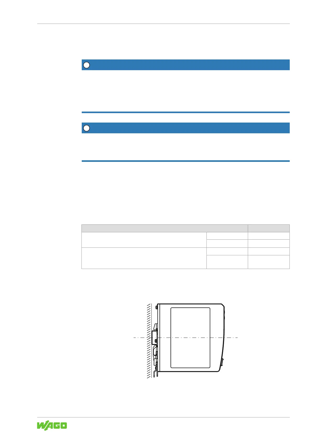
DIN-35 Rail
The DIN-35 rail is located in the center of the vertical axis (height) of the product (see
section 8Technical Data [}18]).
Figure14: Position of the DIN-35 rail
The distances from the central axis of the DIN-35 rail to the top and bottom are 65mm.