Page 103
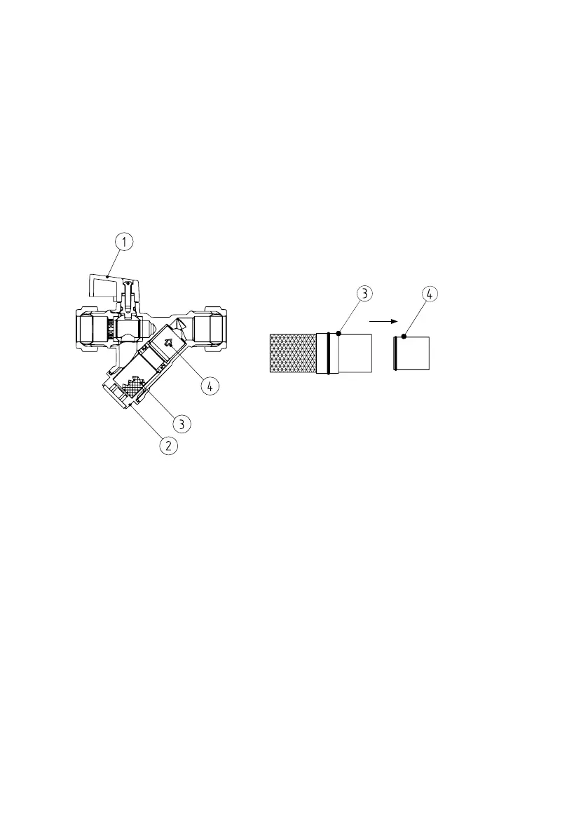
10.3.4 Flow Restrictor
An 18l/min flow restrictor has been factory fitted to the incoming DCW isolation valve, but can
be easily removed if required.
1. Isolate the incoming DCW supply using the ball valve (1).
2. Remove the cap and O ring (2) using a spanner, expect an escape of residual water.
3. Withdraw the combined strainer element (3) and flow restrictor (4) assembly.
4. Remove the flow restrictor cartridge from the strainer element, and replace the strainer
element back into the valve body.
5. Replace the cap, ensuring the O ring is seated correctly.
6. Turn on the incoming DCW supply.
10.3.5 Pipework
All pipework including pipework within the casing should be insulated after the boiler has been
installed. Suitable pipe insulation with a minimum wall thickness of 19mm should be used
wherever possible. For exterior pipework insulation, please see the latest local building
regulations for details.
10.3.6 Balanced flue
Due to the relatively high ambient temperature within the Combination Boiler casing, a balanced
flue should be fitted in order to draw in cooler outside air. For external models, an air inlet
adapter, AID, is available from Warmflow.
10.3.7 Plinth / Base
The boiler should be installed on a plinth or base with a thermal break such as non-combustible
solid insulation. This is to minimise heat transfer to the ground and maximise the overall
efficiency of the boiler.