Page 85
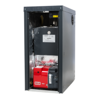
4. Ensure the locking band is open by sliding the clamp to the O (Open) position.
Lubricate and fit the first extension (C) and bend (D) as required by the
installation. Close the locking bands, then slide the clamps to the C (Closed)
position, ensuring the flue is secure
5. Fit the air inlet spigot and gasket to the burner. Attach the flexible air hose to
the burner and starter assembly and secure with the jubilee clips (E) at both ends.
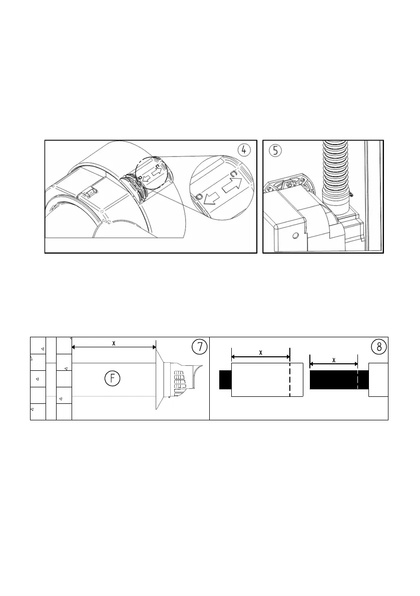
MEASURE AND CUT FLUE TERMINAL
6. Cut a hole through the wall and fit a non-combustible sleeve.
7. Fit the flue terminal (F) and measure the excess length, X.
8. Cut X mm from the outer pipe of the terminal then X mm from the inner pipe.
9. Ensure the locking band is open by sliding the clamp to the O (Open) position.
Lubricate and refit the terminal. Close the locking band, then slide the clamp to the
C (Closed) position, ensuring the flue is secure.
Note: A terminal guard is required if the termination location is less than 2m
above external ground level.