3Preparing the System
30 July 7, 2014, 715003736IVD Rev. C
To power-on the system:
1. Power-on the ACQUITY UPLC I-Class IVD system’s workstation.
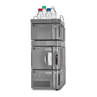
2. Power-on the binary solvent manager and sample manager by pressing
the power switch on the top, left-hand side of each devices’ door.
See also: “Status LEDs” on page 30 and “Power LED” on page 30 for
information on how to interpret LED modes for device or instrument
flow status and whether the units are powered-on.
3. Start MassLynx software.
Tip: You can monitor the ACQUITY UPLC Console for messages and
LED indications.
Monitoring system module LEDs
LEDs on each system module indicate the module’s state of functioning. The
LEDs are specific to their modules, so the significance of their various colors
and modes can differ from one module to another.
Power LED
The power LED, on the left-hand side of a module’s front panel, indicates the
power-on or power-off status of the module. This LED is green when power is
applied to the unit and unlit when power is not applied.
Tip: To provide adequate ventilation, the sample manager fans run
continuously, even when the power switch is in the “off” position. These fans
switch off only when you disconnect the power cable from the back of the
module.
Status LEDs
Flow LED (binary solvent manager)
The flow LED, on the right-hand side of the power LED on the binary solvent
manager’s front panel, indicates the flow status. A steady green flow LED
indicates flow through the binary solvent manager.