8.6 ■ Installation and Wiring Watlow Series F4P
ç
WARNING: To avoid
damage to property and
equipment, and/or injury
or loss of life, use
National Electric Code
(NEC) standard wiring
practices to install and
operate the Series F4P.
Failure to do so could
result in such damage,
and/or injury or death.
ç
CAUTION: Maintain
isolation between analog
inputs 2 and 3, and
between analog input 1
and digital inputs 1- 4 to
prevent a ground loop. A
ground loop may cause
incorrect readings or
error codes. Failure to
follow this guideline
could result in damage to
equipment and product.
ç
WARNING: Process
inputs may not have
sensor break protection.
Outputs can remain full
on.
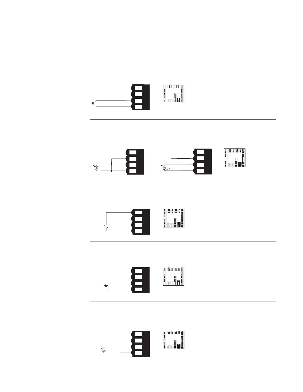
Input 1
Figure 8.6a — Thermocouple
Available on all units.
Impedance: 20MΩ
Figure 8.6b — RTD (2- or 3-Wire) 100, 500 or 1000Ω Platinum
Available on all units.
The last two digits of the model number determine RTD calibration.
Figure 8.6c — 0-5VÎ, 1-5VÎ or 0-10VÎ (dc) Process
Available on all units.
Input impedance: 20kΩ
Figure 8.6d — 0-20mA or 4-20mA Process
Available on all units.
Input impedance: 100Ω
Figure 8.6e — 0 to 50mV
Available on all units
Impedance: 20MΩ

 Loading...


