8.12 ■ Installation and Wiring Watlow Series F4P
Communications Wiring
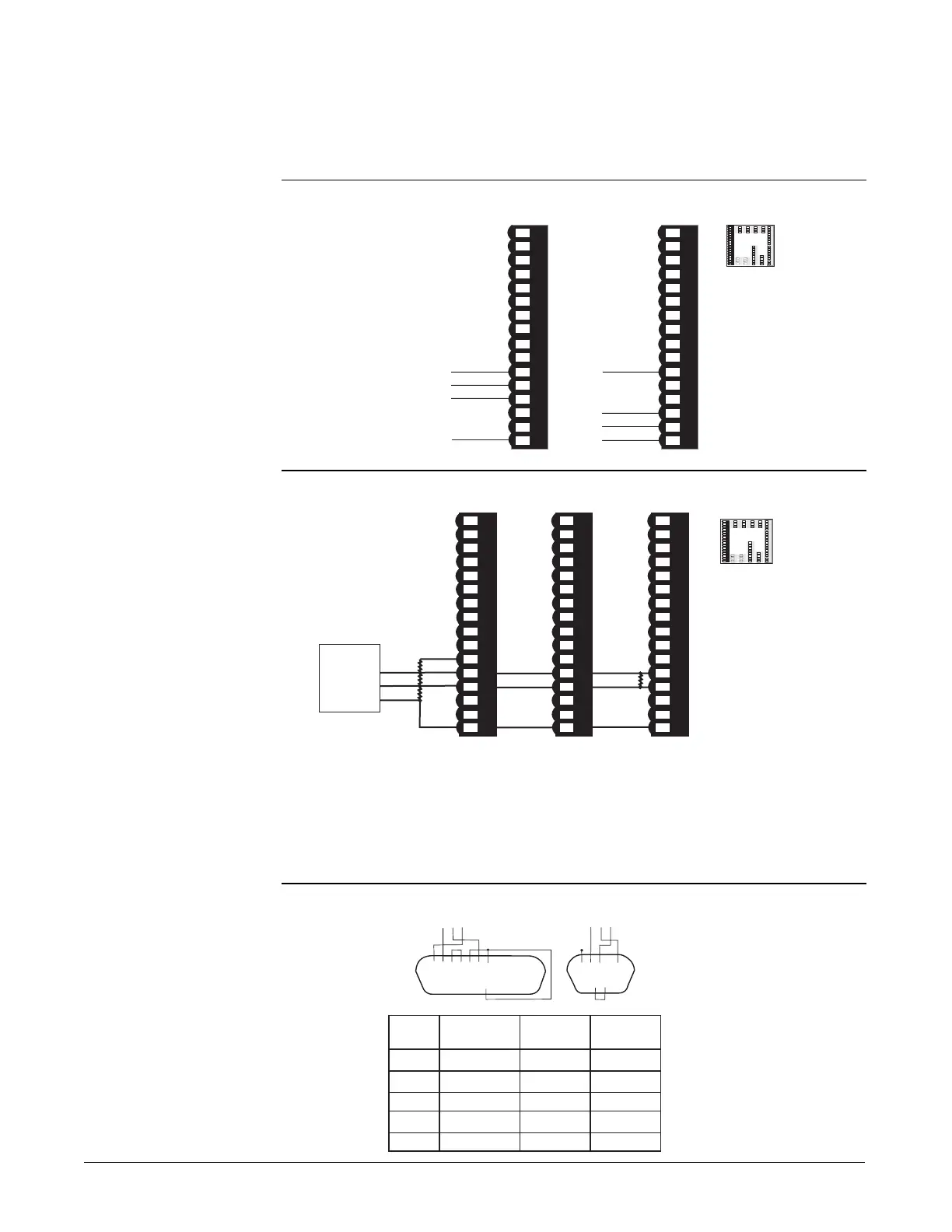
Figure 8.12a — EIA/TIA 485 and EIA/TIA 232 Communications
Figure 8.12b — Termination for EIA-232 to EIA-485 Converter
If the system does not work properly, it may need termination resistors at each
end of the network. A typical installation would require a 120-ohm resistor
across the transmit/receive terminals (12 and 13) of the last controller in the
network and the converter box or serial card. Pull-up and pull-down 1k ohm
resistors may be needed on the first unit to maintain the correct voltage during
the idle state.
Figure 8.12c —
EIA/TIA-232 Connections
• • • • • • • • • • • • •
1 2 3 4 5 6 7 8 9 10 11 12 13
14 15 16 17 18 19 20 21 22 23 24 25
• • • • • • • • • • • •
• • • • •
1 2 3 4 5
6 7 8 9
• • • •
14 16 1514 16 15
Wire F4 DB 9 DB25
Color 232 Connector Connector
White TX Pin 14 RX Pin 2 RX Pin 3
Red RX Pin 15 TX Pin 3 TX Pin 2
Black GND Pin 16 Gnd Pin 5 GND Pin 7
Green GND Pin 24 N/U Pin 9 N/U Pin 22
Shield N/C Gnd Pin 5 Gnd Pin 7
B
A
GND
+5V
T+/R+
T-/R-
1KΩ
120Ω
1KΩ
Converter box
termination
with pull-up
and pull-down
resistors.
1
2
3
4
5
6
7
8
9
10
11 12 13 14
1
5 16
1
2 3
4 5
6 7
8 9
10
11 12
13 14
1
5 16
Com
1
2
3
4
5
6
7
8
9
1
0
1
1
1
2
1
3
1
4
1
5
1
6
1
2
3
4
5
6
7
8
9
1
0
11
1
2
1
3
1
4
1
5
1
6
1
7
1
8
1
9
2
0
2
1
2
2
2
3
2
4
2
5
2
6
2
7
2
8
2
9
3
0
3
1
3
2
1
7
1
8
1
9
20
2
1
22
2
3
2
4
2
5
2
6
2
7
2
8
2
9
3
0
3
1
3
2
59
60 61 62
4
8
4
9
50
45 46 4
7
51
52 53 54 5
5
56
57
58
3
3
3
4
3
5
3
6
3
7
3
8
3
9
4
0
4
1
4
2
4
3
4
4
1
2
3
4
5
6
7
8
9 10 11
12 13 14 15 16
1 2
3 4
5 6
7 8
9
10 11
12 13
14 15 1
6
1
2
3
4
5
6
7
8
9 10 11
12 13 14 15 16
1 2
3 4
5 6
7 8
9
10 11
12 13
14 15 1
6
120Ω
F4P #1 F4P #2 F4P #3 (last unit)
1
2
3
4
5
6
7
8
9
1
0
1
1
1
2
1
3
1
4
1
5
1
6
1 2 3 4 5 6 7 8
9 10 11 12 13
14 15
16
1
7
1
8
1
9
2
0
2
1
2
2
2
3
2
4
2
5
2
6
2
7
2
8
2
9
3
0
3
1
3
2
17 18 19
20 21 22
23 24 2
5
26 27
28 29 30
31 32
5
9
6
0
6
1
6
2
4
8
4
9
5
0
4
5
4
6
4
7
5
1
5
2
5
3
5
4
5
5
5
6
5
7
5
8
3
3
3
4
3
5
3
6
3
7
3
8
3
9
4
0
4
1
4
2
4
3
4
4
11
12
1
2
3
4
5
6
7
8 9 1
0
1
1 12
1
3
1
4 1
5
1
6
1 2
3 4 5 6 7
8 9 10 11 12
13 14 15
16
T+/R+
5V+ termi-
nation bias
13
T-/R-
14
15
1
2
3 4
5
6 7
8
9
1
0
1
1
1
2
1
3
1
4
1
5
1
6
1 2 3 4 5 6 7 8 9 10 11 12 13 14 15 16
Receive
Transmit
16
COM.
EIA/TIA 485 EIA/TIA 232
16COM.
11
5V+ termi-
nation bias
ç
WARNING: To avoid
damage to property and
equipment, and/or injury
or loss of life, use
National Electric Code
(NEC) standard wiring
practices to install and
operate the Series F4P.
Failure to do so could
result in such damage,
and/or injury or death.

 Loading...


