Watlow PM LEGACY™ Limit Controller • 12 • Chapter 1 Overview
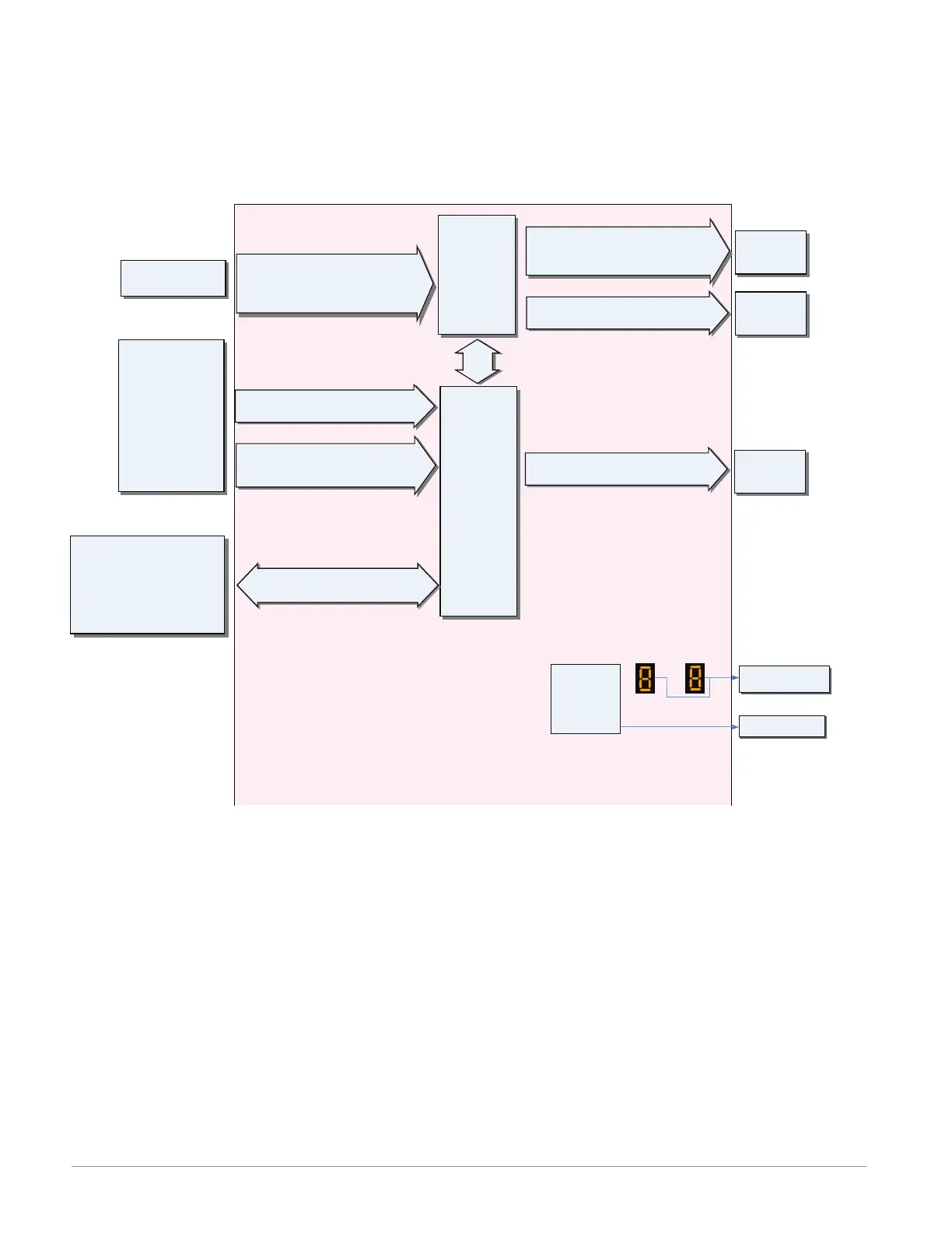
PM LEGACY™ Limit All Models System Diagram
(No communications options 2, 3, 5 or 6)
Universal Sensor Input, Configuration Communications,
Red/Green 7-Segment Display
Analog Input 1
Off, Thermocouple, RTD (100Ω, 1kΩ),
Thermistor (5kΩ, 10kΩ, 20kΩ, 40kΩ),
Process (V, mV, mA, 1k potentiometer)
Output Status
Indicators
5
6
1
3
2
4
Zone
Address
Indicators
Channel
Indicates Zone
Address & Channel*
Indicates I/O
Status
* Channel indicator available
on PM4/8/9 only
Note:
Number of inputs and outputs and various combinations of the same will vary
depending upon part number; see ordering matrix for more detail.
Supervisory
&
Power
Board
Slot C
Limit
Controller
Board
Slot A
EZ-ZONE™ PM Limit Controller
Input
Functions
Output
Functions
Network
Remote User Interface
Personal Computer
Programmable Logic Controller
Human Machine Interface
None
Limit reset
Loop & alarms off
Silence alarm
Force Alarm
Lock keypad
Restore user settings
Input Sensor
EIA 485 Communications
Standard Bus, Modbus RTU (optional)
Function Key
(Not available on 1/32 DIN)
Programmable Functions
Digital Input (or Output) 5 & 6
(optional) none, switch, volts dc
Output 2
Form A mechanical (5 A) relay
Output 1
None, Switched dc/open collector,
Form C mechanical (5 A) relay
Off, Limit,
Alarm
Digital Output (or Input) 5 & 6
(optional) None, Switched dc
Off,
Alarm
Limit

 Loading...


