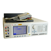
Connectors on the rear
On the rear of the D-AMPS module (slot 5/6), you can find various connectors.
This section explains what they can be used for.
"
Not all of these signals are available all the time. If you require some of them and
you do not find them operational, please contact Wavetek for a special application
software.
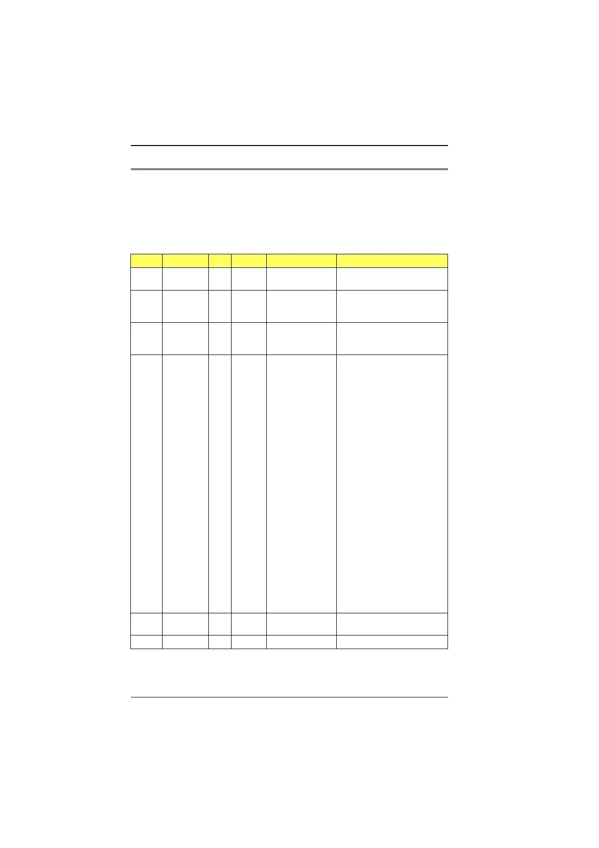
Socket Signal Dir. Ri Vmax Application
Bu 103 IF in 270 Ω±14 V External IF signal feed from
Bu 103 on slot 3
Bu 104 AF in 3 kΩ
(approx.)
±5 V Reserved
Bu 105 RS-232 in/out For external control, see
section "RS-232 interface" in
this option manual
Bu 106 AUX
Pin 1
Pin 2
Pin 3
Pin 4
Pin 5
Pin 6
Pin 7
Pin 8
Pin 9
Pin 10
Pin 11
Pin 12
Pin 13
Pin 14
Pin 15
Pin 16
Pin 17
Pin 18
Pin 19
Pin 20
Pin 21
Pin 22
Pin 23
Pin 24
Pin 25
AnalogInI
AnalogInQ
GND
GND
GND
GND
ITXout
QTXout
GND
GND
GND
GND
QoutM
IoutM
ext Q
ext I
GND
QRX
IRX
GND
Vcc
GND
–15 V
GND
+15 V
in
in
out
out
out
out
in
in
out
out
3 kΩ
3 kΩ
5 kΩ
5 kΩ
±5 V
±5 V
2.5 V ±2.5 V
p
2.5 V ±2.5 V
p
2.5 V ±2.5 V
p
2.5 V ±2.5 V
p
\ Input for external I/Q signal
/ (TX, IF)
\ Analog I/Q TX signals
/ output
\ RX signal, I/Q
/
\ Input from fading simulator
/
\ Output to fading simulator
/ (RX I/Q signals)
Bu 107 SYNC in TTL TTL External synchronization,
negative pulse > 125 ns
Bu 108 SYNC out External synchronization
TETRA MS Test Appendix
10-54