Do you have a question about the Wecon VM Series and is the answer not in the manual?
Crucial warnings about potential severe injury or death from improper handling.
Guidelines for safe installation, ventilation, wiring, and environmental conditions.
Detailed warnings on wiring, grounding, touching terminals, and power disconnection.
Key technical data including input/output voltage, frequency, protection level, and temperature.
Explanation of the product nameplate and the VM series model naming convention.
Table detailing different models, their power, input voltage, and output current ratings.
Visual guide showing physical dimensions and mounting hole details.
Diagrams illustrating input/output and control terminal connections for different power ratings.
Detailed description of each terminal and its function in the main circuit.
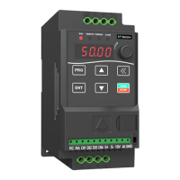
Identification of keypad buttons, LED indicators, and their functions.
Step-by-step guide on using the keypad for parameter settings and control.
Introduction to functional parameters and settings for frequency source and control.
Parameters for fan control, start options, speed tracking, and braking.
Parameters for motor type, rated values, and protection settings.
Parameters for motor auto-tuning, G/P models, and linear/customized VF curves.
Parameters for VF curve points, oscillation suppression, and digital input functions.
Parameters for DI terminal features, analog input/output signals, and filter settings.
Parameters for virtual VDO output, AO1 output signal settings, and relay output delays.
Parameters for user-defined logic, keypad display values, and security settings.
Parameters for display values, accumulated values, and jog run settings.
Parameters for acceleration/deceleration times, hopping, dead zone, and PID switching.
Detailed parameters for PID control, including gains, times, deviations, and switching conditions.
Further PID control parameters like integral property, feedback alarm, and sleep mode.
Parameters for various protection mechanisms like overcurrent, overvoltage, and phase loss.
Parameters for Modbus communication baud rate, data format, and PLC stage settings.
Settings for Inner PLC stages 0 through 9, covering running period and time.
Settings for Inner PLC stages 2 through 9, covering direction and acceleration/deceleration time.
Settings for Inner PLC stages 10 through 15, covering running period and time.
Parameters for PLC running options, multi-stage speed, priority, and user password.
Table listing parameters for monitoring the drive's operational status and values.
Comprehensive list of error codes, their possible causes, and recommended solutions.
Introduction to RS485 communication and Modbus protocol support.
Explanation of RAM and EEPROM address conversion for communication.
Detailed register map for controlling and monitoring the drive via RS485.
List of communication failure codes and their descriptions.