CFW-11 | 3-5
3.1.3 Cabinet Mounting
It is possible to mount the inverters in two manners, either on the mounting surface, or with the heatsink mounted
outside the cabinet, so that the air for cooling the power heatsink is kept outside the enclosure (flange mounting).
For these cases, consider:
Surface mounting:
Provide adequate exhaustion, so that the internal cabinet temperature remains within the allowed range for
the inverter operation conditions.
The power dissipated by the inverter at its rated condition, as specified in Table 8.1 on page 8-2 in the
column "Power dissipated in watts, surface mount".
Cooling air flow according to the Table 3.1 on page 3-5.
The position and diameter of the mounting holes according to the Figure 3.1 on page 3-3.
Flange mounting:
ATTENTION!
The part of the inverter that stays outside the cabinet is rated IP20. See Section 8.2 ELECTRONICS/
GENERAL DATA on page 8-6.
The power specified in Table 8.1 on page 8-2 will be dissipated inside the cabinet. The other losses (power
modules) will be dissipated at the external ventilation duct.
The inverter mounting supports and the hoisting eyes must be removed. Refer to the Figure 2.4 on page
2-10, positions I and J.
Dimensions of the flange-mounting opening and the diameters of the securing holes must be according to
the Figure 3.1 on page 3-3.
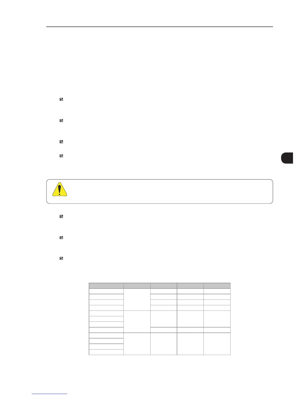
Table 3.1 - Cooling air ow for frame sizes F, G and H models
Model Frame Size CFM I/s m³/min
CFW110242T4
F
250 118 7.1
CFW110312T4 320 151 9.1
CFW110370T4 380 180 10.1
CFW110477T4 460 217 13.0
CFW110515T4
G
680 321 19.3CFW110601T4
CFW110720T4
CFW110760T4 1020 481 28.9
CFW110795T4
H 1100 520 31.2
CFW110877T4
CFW111062T4
CFW111141T4