3-44 | CFW-11
In order to drive the motor again, it is required to apply STO1 and STO2 signals again (to close terminals 13
to 23 and 23 to 24) and apply a pulse on inverter DI1 input (START).
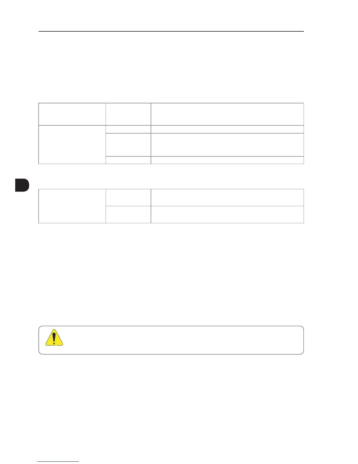
3.3.4 Technical Specifications
3.3.4.1 Electrical Control Characteristics
Safety stop function inputs XC25:1-2, XC25:3-4 2 independent inputs for Safety Stop function
Power supply: 24 Vdc (max. 30 V)
Impedance: 960 Ω
State 0 if < 2 V, state 1 if > 17 V
External safety relay specifications
(only when SS1 function is required
according to IEC/EN 61800-5-2
and IEC/EN 60204-1 standards)
refer to Figure 3.26 on page 3-43
General requirements IEC 61508 and/or EN 954-1 and/or ISO 13849-1
Output requirements Number of current paths: 2 independent paths (one for each STO path)
Switching voltage capability: 30 Vdc per contact
Switching current capability: 100 mA per contact
Maximum switching delay between contacts: 100 ms
Example Type/manufacturer: WEG/Instrutech CPt-D
3.3.4.2 Operational Safety Characteristics
Protection Of the machine Safety Stop function which forces stopping and/or prevents the motor from
restarting unintentionally, conforming to EN 954-1 / ISO 13849-1 category 3,
IEC/EN 61800-5-2 and IEC/EN 60204-1
Of the system process Safety Stop function which forces stopping and/or prevents the motor from
restarting unintentionally, conforming to IEC/EN 61508 level SIL2 and IEC/EN
61800-5-2
3.4 INSTALLATION ACCORDING TO THE EUROPEAN DIRECTIVE OF ELECTROMAGNETIC
COMPATIBILITY
The CFW-11 inverters with frame sizes F, G and H feature internal RFI filter to reduce the electromagnetic
interference.
These inverters, when properly installed, meet the requirements of the electromagnetic compatibility directive
‘’EMC Directive 2014/30/EU’’.
The CFW-11 inverter series has been designed only for industrial applications. Therefore, the emission limits
of harmonic currents defined by the standards EN 61000-3-2 and EN 61000-3-2/A14 are not applicable.
ATTENTION!
For using models with internal RFI filters in IT networks follow the instructions on Item 3.2.3.1.2 IT
Networks on page 3-22.
3.4.1 Conformal Installation
For the conformal installation use:
1. Shielded output cables (motor cables) with the shield connected at both ends, motor and inverter, by means
of a low impedance to high frequencies connection.
Use the clamps supplied with the product, making sure there is a good contact between the shield and that
clamp.