3-38 | CFW-11
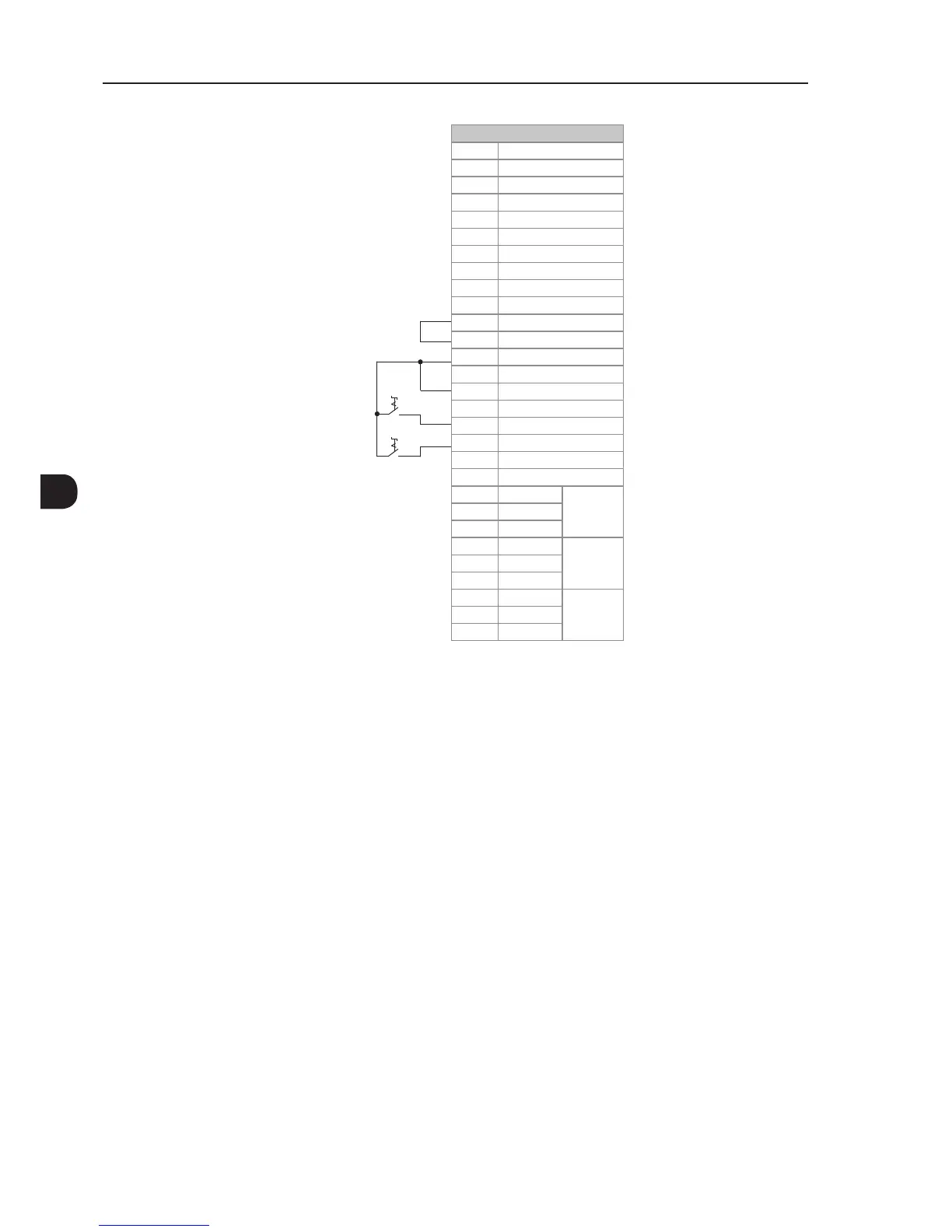
Stop/Forward S1
Stop/Reverse S2
XC1 Terminal Strip
1 + REF
2 AI1+
3 AI1-
4 - REF
5 AI2+
6 AI2-
7 AO1
8 AGND (24 V)
9 AO2
10 AGND (24 V)
11 DGND*
12 COM
13 24 Vdc
14 COM
15 DI1
16 DI2
17 DI3
18 DI4
19 DI5
20 DI6
21 NF1
DO1
(RL1)
22 C1
23 NA1
24 NF2
DO2
(RL2)
25 C2
26 NA2
27 NF3
DO3
(RL3)
28 C3
29 NA3
Figure 3.24 - XC1 wiring for control connection 4
3.3 SAFETY STOP FUNCTION
The inverters CFW11...O...Y... have the board SRBXX that implements Safety Stop function. Through this board it
is possible to control two safety relays (K1 and K2) that actuate directly on the power circuit, more specifically on
the IGBTs gate drivers power supply. The basic functional block diagram is shown in Figure 3.25 on page 3-39.
The safety relays guarantee that the IGBTs remain switched off when Safety Stop function is activated, even in
case of an internal single failure. The position of SRBXX board and XC25 terminals (Safety Stop control terminals)
on the inverter is shown in Figure 3.18 on page 3-33.
The Safety Stop function prevents the motor starting accidentally.