CFW-11 | 3-23
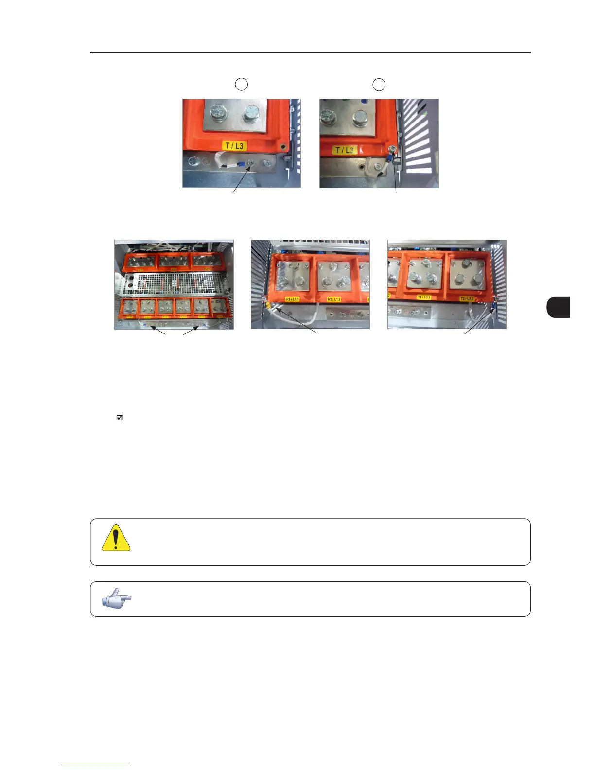
2
1
Remove
Connect
(a) Initial position (b) Final position (IT)
Figure 3.11 - (a) and (b) - Ground connections - location and procedure for adapting to IT or corner-ground networks
(a) Initial position (b) Final position (IT) (c) Final position (IT)
Remove
Connect Connect
Figure 3.12 - Grounding connections – location and procedure to adapt to the IT or delta-grounded networks – frame size H
3.2.3.1.3 Command Fuses of Pre-charge Circuit
Specifications of the used auxiliary fuse:
4 A / 690 V slow blow fuse.
Manufacturer: Ferraz Shawmut.
Commercial reference: 17019-G.
WEG part number 10411503.
3.2.3.2 Dynamic Braking
ATTENTION!
Frame sizes F, G and H models do not have internal braking IGBT. When necessary, braking modules
and external resistors should be installed, as shown in Figure 3.13 on page 3-24.
NOTE!
Set P0151 and P0185 to the maximum value (800 V) when using dynamic braking.
The braking torque that can be obtained using frequency inverters without dynamic braking varies between 10 %
to 35 % of the motor rated torque.
In order to obtain higher braking torques, resistors for dynamic braking must be used. In this case, the energy
regenerated in excess is dissipated on a resistor mounted outside the inverter.