3-24 | CFW-11
This type of braking is used in cases when short deceleration times are desired or when high inertia loads are
driven.
For the vector control mode, there is the possibility of using the "Optimal Braking", eliminating in many cases
the need of dynamic braking use.
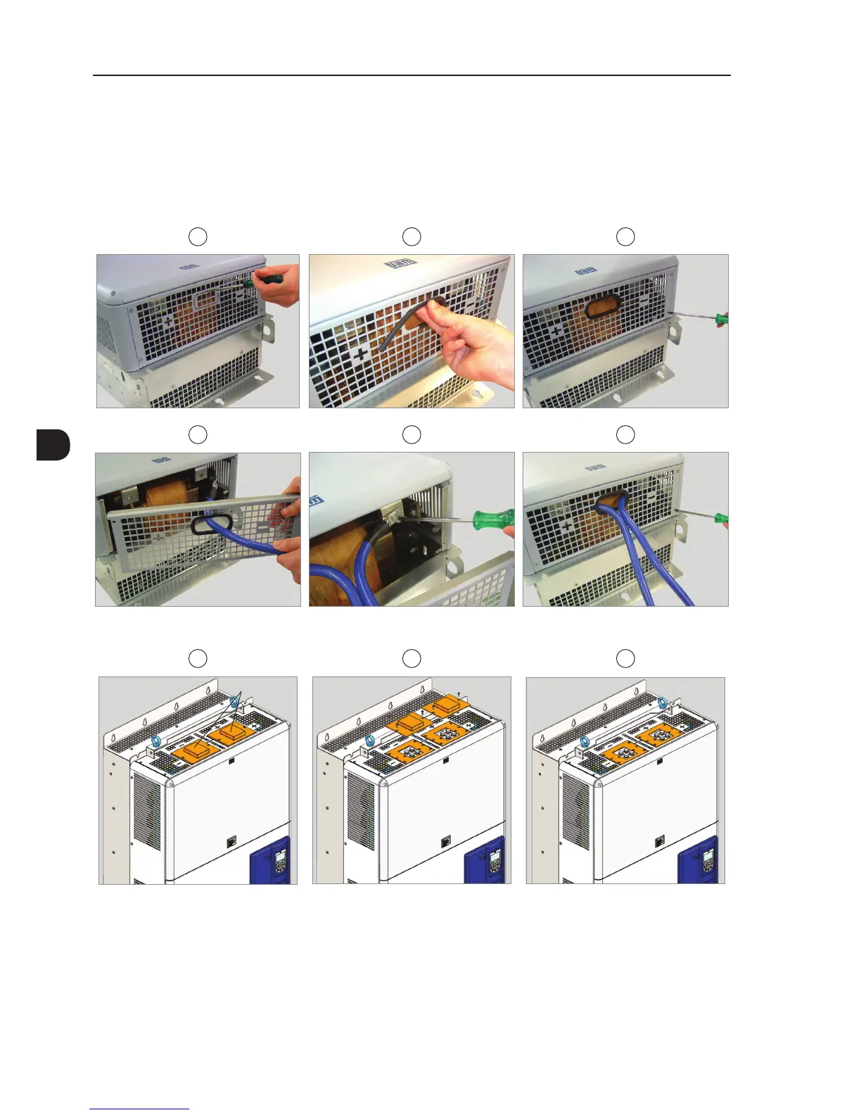
1 2 3
4 5 6
(a) Frame sizes F and G
1 2 3
Remove cover
(b) Frame size H
Figure 3.13 - (a) and (b) - Sequence for the connection cables of DC+ and DC- for connection of an external braking
module to CFW-11 inverter