CFW-11 | 3-29
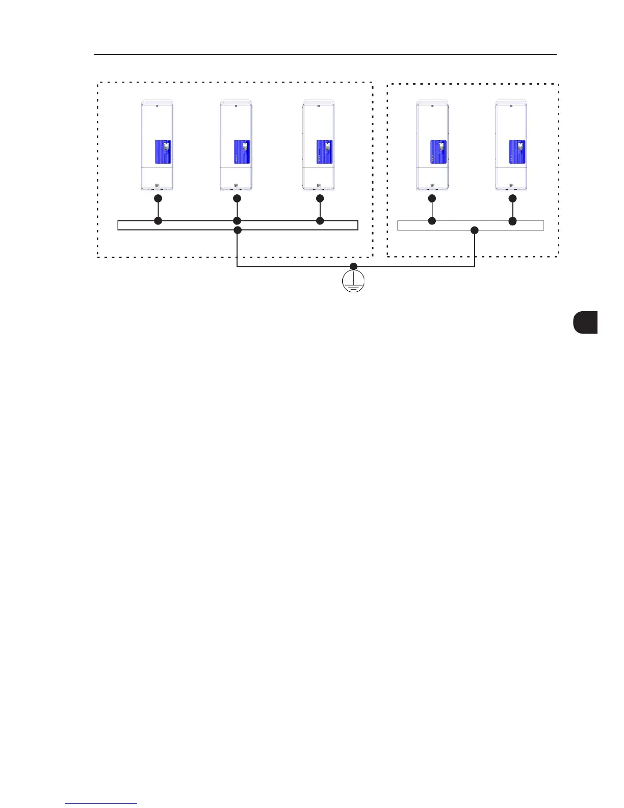
Cabinet internal ground busbar
CFW-11 nº1 CFW-11 nº2
CFW-11 nºN
CFW-11 nº2
CFW-11 nº1
Figure 3.15 - Grounding connections with multiple inverters
3.2.5 Control Connections
The control connections (analog inputs/outputs, digital inputs/outputs), must be made at the CC11 control
board terminal strip XC1.
Functions and typical connections are presented in Figure 3.16 on page 3-31.