3-30 | CFW-11
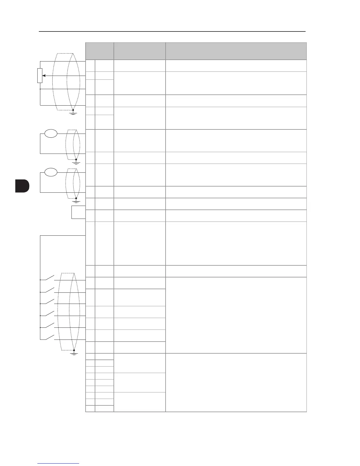
XC1
Terminal
Strip
Factory Setting Function Specications
1 +REF Positive reference for
potentiometer
Output voltage:+5.4 V, ±5 %
Maximum output current: 2 mA
2 AI1+ Analog input 1:
Speed reference (remote)
Differential
Resolution: 12 bits
Signal: 0 to10 V (R
IN
= 400 kΩ) / 0 to 20 mA / 4 to 20 mA (R
IN
= 500 Ω)
Maximum voltage: ±30 V
3 AI1-
4 REF- Negative reference for
potentiometer
Output voltage: -4.7 V, ±5 %
Maximum output current: 2 mA
5 AI2+ Analog input 2:
no function
Differential
Resolution: 11 bits + signal
Signal: 0 to ±10 V (R
IN
= 400 kΩ) / 0 to 20 mA / 4 to 20 mA (R
IN
= 500 Ω)
Maximum voltage: ±30 V
6 AI2-
7 AO1 Analog output 1:
speed
Galvanic Isolation
Resolution: 11 bits
Signal: 0 to 10 V (R
L
≥ 10 kΩ) / 0 to 20 mA / 4 to 20 mA (R
L
≤ 500 Ω)
Protected against short-circuit
8 AGND
(24 V)
Reference (0 V) for the
analog outputs
Connected to the ground (frame) through an impedance: 940 Ω resistor
in parallel with a 22 nF capacitor. Same reference as the one of DGND *
9 AO2 Analog output 2:
motor current
Galvanic isolation
Resolution: 11 bits
Signal: 0 to 10 V (R
L
≥ 10 kΩ) / 0 to 20 mA / 4 to 20 mA (R
L
≤ 500 Ω)
Protected against short-circuit
10 AGND
(24 V)
Reference (0 V) for the
analog outputs
Connected to the ground (frame) through an impedance: 940 Ω resistor
in parallel with a 22 nF capacitor. Same reference as the one of DGND *
11 DGND
*
Reference (0 V) for the
24 Vdc power supply
Connected to the ground (frame) through an impedance: 940 Ω resistor
in parallel with a 22 nF capacitor. Same reference as the one of AGND (24 V)
12 COM Common point of the
digital inputs
13 24 Vdc 24 Vdc power supply 24 Vdc power supply, ±8 %
Capacity: 500 mA
Note: In the models with the 24 Vdc external control power supply
(CFW11...O...W...) pin 13 o XC1 is considered na input, that is, the user
must provide a supply for the inverter (for further details refer to Item 7.1.2
24 Vdc External Control Power Supply on page 7-1). In all the other
models this terminal is an output, i.e., the user has a 24 Vdc power supply
available there
14 COM Common point of the
digital inputs
15 DI1 Digital input 1:
Start/Stop
6 isolated digital inputs
High level ≥ 18 V
Low level ≤ 3 V
Maximum input voltage = 30 V
Input current: 11 mA @ 24 Vdc
16 DI2 Digital input 2:
Direction of rotation
(remote)
17 DI3 Digital input 3:
no function
18 DI4 Digital input 4:
no function
19 DI5 Digital input 5:
Jog (remote)
20 DI6 Digital input 6:
2
nd
ramp
21 NF1 Digital output 1 DO1
(RL1): No fault
Contact rating:
Maximum voltage: 240 Vac
Maximum current: 1 A
NF - normally closed contact
C - common
NA - normally open contact
22 C1
23 NA1
24 NF2 Digital output 2 DO2
(RL2):
N > N
X
- speed > P0288
25 C2
26 NA2
27 NF3 Digital output 3 DO3
(RL3): N* > N
X
- speed
reference > P0288
28 C3
29 NA3
CCW
CW
≥5 kΩ
rpm
amp
(a) Signals at connector XC1 - Digital inputs working as "active high"