3-46 | CFW-11
Class B: equipment intended for use in the low-voltage power supply network (residential, commercial, and
light-industrial environments).
Class A1: equipment intended for use in the low-voltage power supply network. Restricted distribution.
Note: must be installed and commissioned by a professional when applied in the low-voltage power supply
network.
Class A2: equipment intended for use in industrial environments.
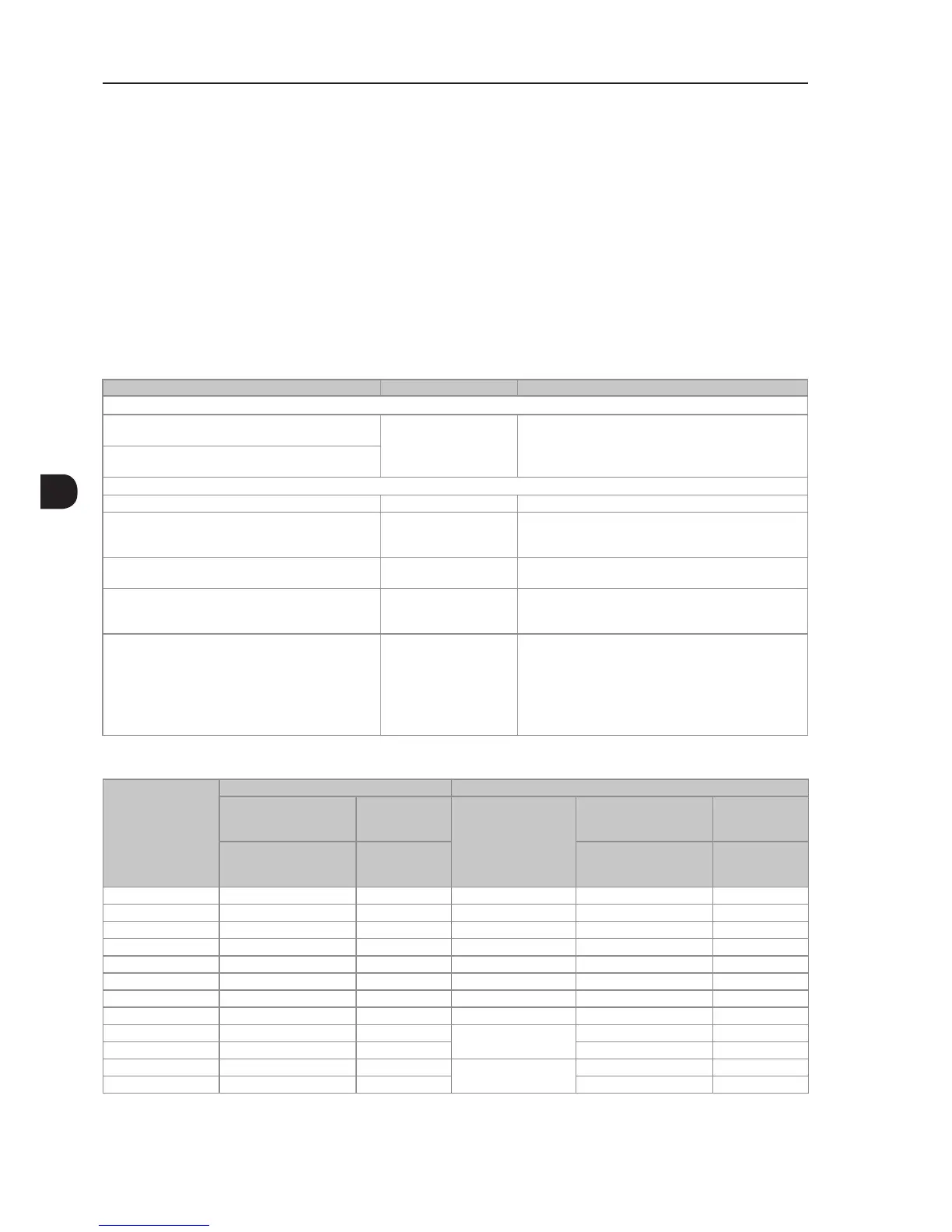
3.4.3 Emission and Immunity Levels
Table 3.14 - Emission and immunity levels
EMC Phenomenon Basic Standard Level
Emission:
Mains terminal disturbance voltage
Frequency range: 150 kHz to 30 MHz
IEC/EN61800-3 (2004) +
A1 (2011)
It depends on the inverter model and on the motor cable
lenght. Refer to Table 3.15 on page 3-46
Electromagnetic radiation disturbance
Frequency range: 30 MHz to 1000 MHz
Immunity:
Electrostatic discharge (ESD) IEC 61000-4-2 (2008) 4 kV for contact discharge and 8 kV for air discharge
Fast transient-burst IEC 61000-4-4 (2012) 2 kV / 5 kHz (coupling capacitor) power input cables
1 kV / 5 kHz control cables, and remote keypad cables
2 kV / 5 kHz (coupling capacitor) motor output cables
Conducted radio-frequency common mode IEC 61000-4-6 (2013) 0,15 to 80 MHz; 10 V; 80 % AM (1 kHz)
Motor cables, control cables, and remote keypad cables
Surge immunity IEC 61000-4-5 (2014) 1,2/50 µs, 8/20 µs
1 kV line-to-line coupling
2 kV line-to-ground coupling
Radio-frequency electromagnetic field IEC 61000-4-3 (2010) 80 MHz to 1000 GHz
10 V/m
1,4 GHz to 2GHz
3 V/m
2 GHz to 2,7 GHz
1 V/m
80 % AM (1 kHz)
Table 3.15 - Conducted and radiated emission levels
Inverter Model
Without External RFI Filter With External RFI Filter
Conducted Emission
- Maximum Motor
Cable Length
Radiated
Emission
External
RFI Filter
Part Number
(Manufacturer Epcos)
Conducted Emission -
Maximum Motor Cable
Length
Radiated
Emission
Category C3
Category
without Metal
Panel
Category C2
Category with
Metal Panel
CFW110242T4 100 m C3
(1)
B84143-B0250-S020 50 m
(3)
C3
CFW110312T4 100 m C3
(1)
B84143-B0320-S020 50 m
(3)
C3
CFW110370T4 100 m C3
(1)
B84143-B0400-S020 50 m
(3)
C3
CFW110477T4 100 m C3
(1)
B84143-B0600-S020 50 m
(3)
C3
CFW110515T4 100 m C3
(1)
B84143-B0600-S020 50 m
(3)
C3
CFW110601T4 100 m C3
(1)
B84143-B0600-S020 50 m
(3)
C3
CFW110720T4 100 m C3
(1)
B84143-B1000-S020 50 m
(3)
C3
CFW110760T4 100 m C4
(2)
B84143-B1000-S020 - -
CFW110795T4 100 m C4
(2)
B84143-B1000-S80
- -
CFW110877T4 100 m C4
(2)
- -
CFW111062T4 100 m C4
(2)
B84143-B1250-S80
- -
CFW111141T4 100 m C4
(2)
- -
(1) With toroidal core in the three line power supply cables (the three cables connected to R/L1, S/L2 and T/L3 must pass through a single toroidal core).
Example: TDK PN: PC40U120x160x20 ironxclube PN: U126x91x20-3F3. If the installation of the inverter is done inside the panel with attenuation of 10
dB in the frequency adjustable range [30; 50] mHz), the toroidal core is not necessary.
(2) For further details, contact WEG.
(3) Minimum operating frequency of 2.5 Hz.