CFW-11 | 3-39
XC25:1 XC1
XC25:3
X1:
DC+
X1:
DC-
V1
V1
S1
S1
S2
S2
K1
K2
+5 V
+5 V
2
4
X1:
X1
R/L1
U/T1
Rectifier
DC Link
capacitors
Gate
driver
circuit
Gate
driver
circuit
Gate
driver
circuit
Gate
driver
circuit
Gate
driver
circuit
Gate
driver
circuit
Digital (Relay)
outputs
S/L2
V/T2
Motor
T/L3
W/T3
SR1
SR2
Control circuit (Microcontroller+EPLD)
PWM1
PWM3
PWM5
PWM6
PWM4
PWM2
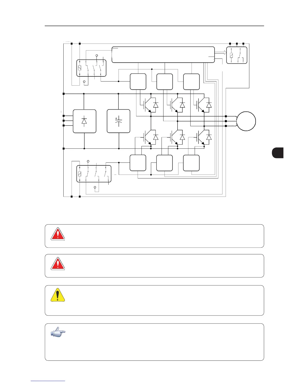
Note:
V1 = inverter internal voltage.
Figure 3.25 - Basic block diagram of Safety Stop function available in CFW-11 inverter series
DANGER!
The activation of the Safety Stop function does not guarantee electrical safety of the motor terminals
(they are not isolated from the power supply in this condition).
DANGER!
L'activation de la fonction d'arrêt de sécurité ne garantit pas la sécurité électrique des bornes du
moteur (elles ne sont pas isolées de l'alimentation électrique dans cet état).
ATTENTION!
In case of a multiple fault in the power stage of the inverter, the motor shaft can rotate up to 360/
(number of poles) degrees even with the activation of Safety Stop function. That must be considered in
the application.
NOTE!
Inverter Safety Stop function is only one component of the safety control system of a machine and/
or process. When inverter and its safety stop function is correctly used and with other safety components,
it’s possible to fulfill the requirements of standard EN 954-1/ISO 13849-1, Category 3 (machine safety)
and IEC/EN 61508, SIL2 (safety control/signaling applied to processes and systems).