3-20 | CFW-11
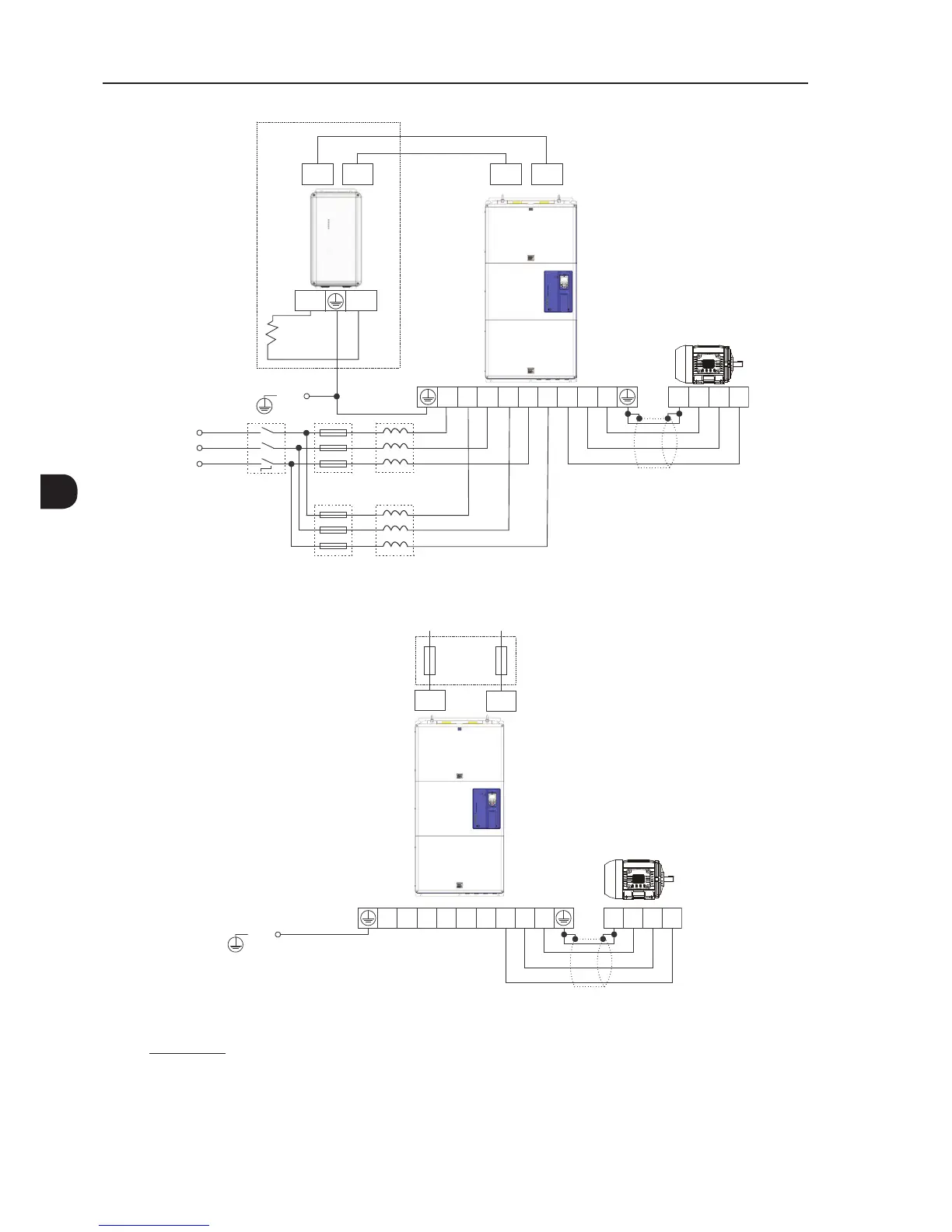
Shielding
Disconnect
switch
Fuses
Fuses
T
S
R
PE
R1 R2
DC+ BR
S1 S2 T1 T2 U V W
PE W V U
Power
supply
DC+ DC+DC-DC-
Optional
External
braking
module
Braking
resistor
Line reactor
(1)
Line reactor
(1)
(a) Models with AC power supply (IP20 degree of protection) - frame size H
Shielding
Fuses
PE
R1
R2 S1 S2 T1 T2 U V W
PE W V U
DC+
DC-
DC power supply
(3)
(b) Models with direct current power supply (IP00 degree of protection) - special hardware DC
(2)
- frame size H
(1) For frame size H models, two line reactances are required with minimum voltage drop of 3 % under rated condition of the inverter.
L = 919 . [µH]
∆V [%] . V
LL
[V]
f
R
[Hz] . I [A]
∆V = Percentage voltage drop.
V
LL
= Inverter supply line voltage.
f
R
= Line frequency.
I = Reactor current. Consider half the inverter input current for each reactor and an unbalance of 15 %. For example, in model 1141 A, the maximum
current of each reactor is 1.15 (1141/2) = 656 A.
(2) Alternatively, the standard model of frame size H can also be supplied in DC current via terminals "DC-" and "DC+".
(3) According to Chapter 8 TECHNICAL SPECIFICATIONS on page 8-1, Table 8.2 on page 8-3.
Figure 3.10 - (a) and (b) - Power and grounding connections - frame size H