CFW-11 | 3-27
Table 3.6 - Minimum separation distance between motor cables and all other cables
Cable Length Minimum Separation Distance
≤ 30 m (100 ft) ≥ 10 cm (3.94 in)
> 30 m (100 ft) ≥ 25 cm (9.84 in)
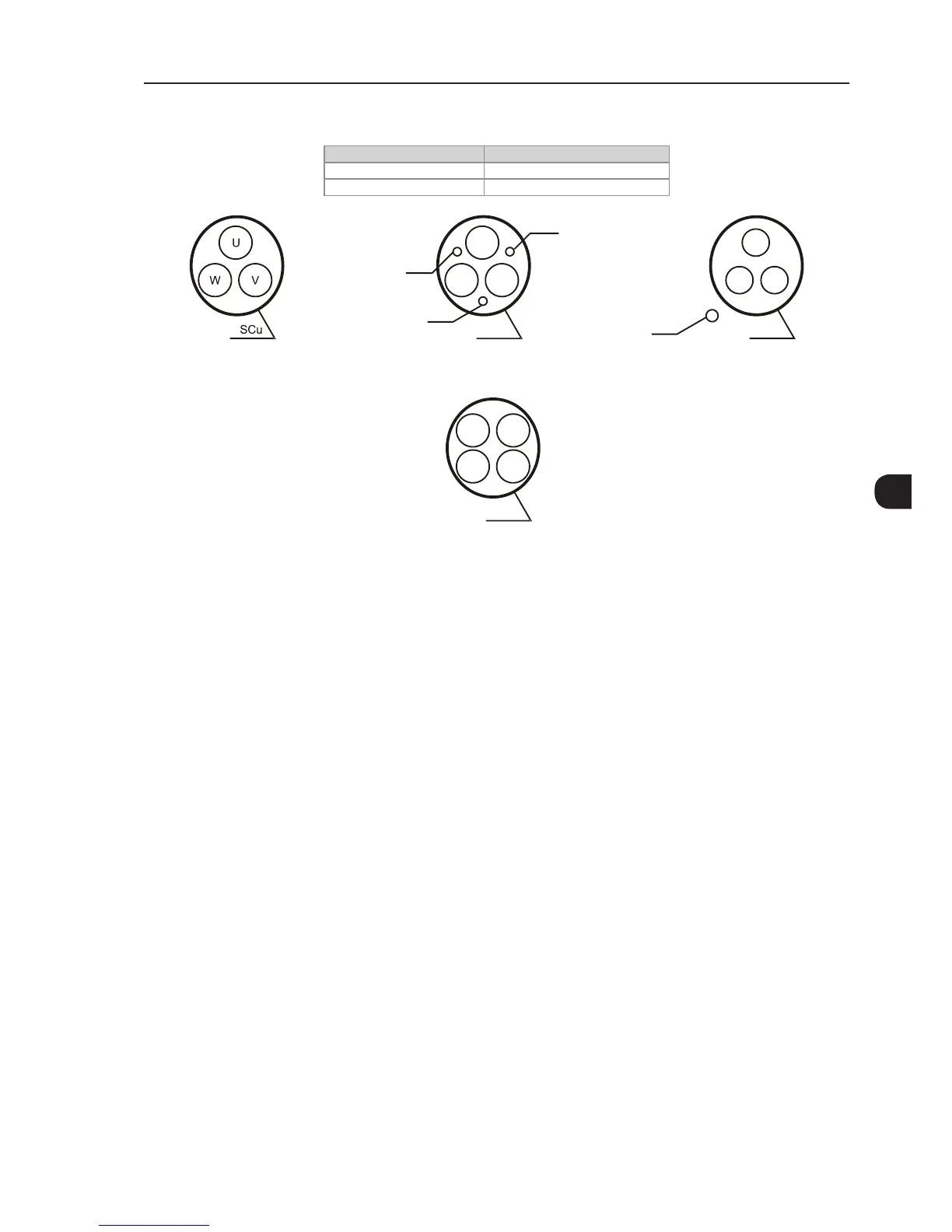
(a) Symmetrical shielded cables: three concentric conductors with or without a ground conductor, symmetrically
manufactured, with an external shield of copper or aluminum
(b) Alternatives for conductors up to 10 mm
2
(1) SCu = copper or aluminum external shielding.
(2) AFe = galvanized steel or iron.
(3) PE = ground conductor.
(4) Cable shielding must be grounded at both ends (inverter and motor). Use 360º connections for low impedance to high frequencies.
(5) For using the shield as a protective ground, it must have at least 50 % of the power cables conductivity. Otherwise, add an external ground
conductor and use the shield as an EMC protection.
(6) Shielding conductivity at high frequencies must be at least 10 % of the phase power cable conductivity.
Figure 3.14 - (a) and (b) - Motor connection cables recommended by IEC 60034-25