9
I/O
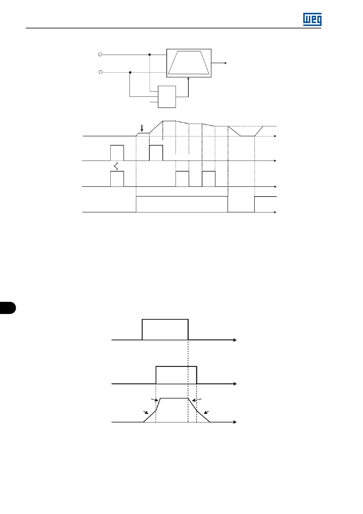
Output
frequency
Time
Time
Time
Time
Reference
DIx - Accelerate
DIx - Accelerate
DIx - Decelerate
DIx - Run/Stop
DIx - Decelerate
Inactive
Active
Inactive
Active
Inactive
Active
RAMP
Enabling (RUN)
P133
Reset Speed
Reset
&
Figure 9.13: Example of the Electronic Potentiometer (E.P.) function
j) MULTISPEED
The Multispeed reference, as described in Section 7.2 SPEED REFERENCE on page 7-6, enables, by means
of the combination of up to three digital inputs, the selection of one from eight reference levels predefined in
parameters P124 to P131.
For further details, refer to Chapter 7 COMMAND AND REFERENCES on page 7-1.
k) 2
nd
RAMPA
If DIx is inactive, the inverter uses the default ramp by P100 and P101, otherwise, it will use the 2
nd
Ramp by
P102 and P103 (Figure 9.14 on page 9-18).
Output
frequency
Time
Time
Time
P103
P101
DIx - 2
nd
ramp
DIx - Run/Stop
Inactive
P102
Inactive
Active
P100
Active
Figure 9.14: Example of the 2
nd
Ramp function
l) NO EXTERNAL ALARM
If DIx is inactive, the inverter will activate the external alarm A090.
m) NO EXTERNAL FAULT
If DIx is inactive, the inverter will activate the external fault F091. In this case, the PWM pulses are disabled
immediately.
9-18 | Micro Mini Drives