14
APPLICATIONS
The example below defines the terms used by the PID controller application.
An electric pump used in a water pumping system in which the pressure must be controlled at the pump output pipe.
A pressure transducer is installed on the pipe and provides an analog feedback signal to the inverter proportional to
the water pressure. That signal is called process variable and can be viewed in parameter P916. A control setpoint
is programmed in the inverter via HMI (P911), or via analog input (AI1 or AI2), or via electronic potentiometer
function (DI3 and DI4), or via logical combination of digital inputs DI3 and DI4 according to the control setpoint
source defined in P920. The control setpoint is the water pressure which the pump must produce regardless of
the demand variations in the pump output at any moment.
In order to enable the operation of the PID controller application, it is necessary to program the speed reference
for the SoftPLC function, that is, parameter P221 or P222 in 12 = SoftPLC, and select the PID controller control
action in P928 for direct action (=1) or reverse action (=2), thus enabling the PID operation. Otherwise, the alarm
message “A790: Speed reference source (P221 or P222) not programmed for the SoftPLC (12)” will be generated.
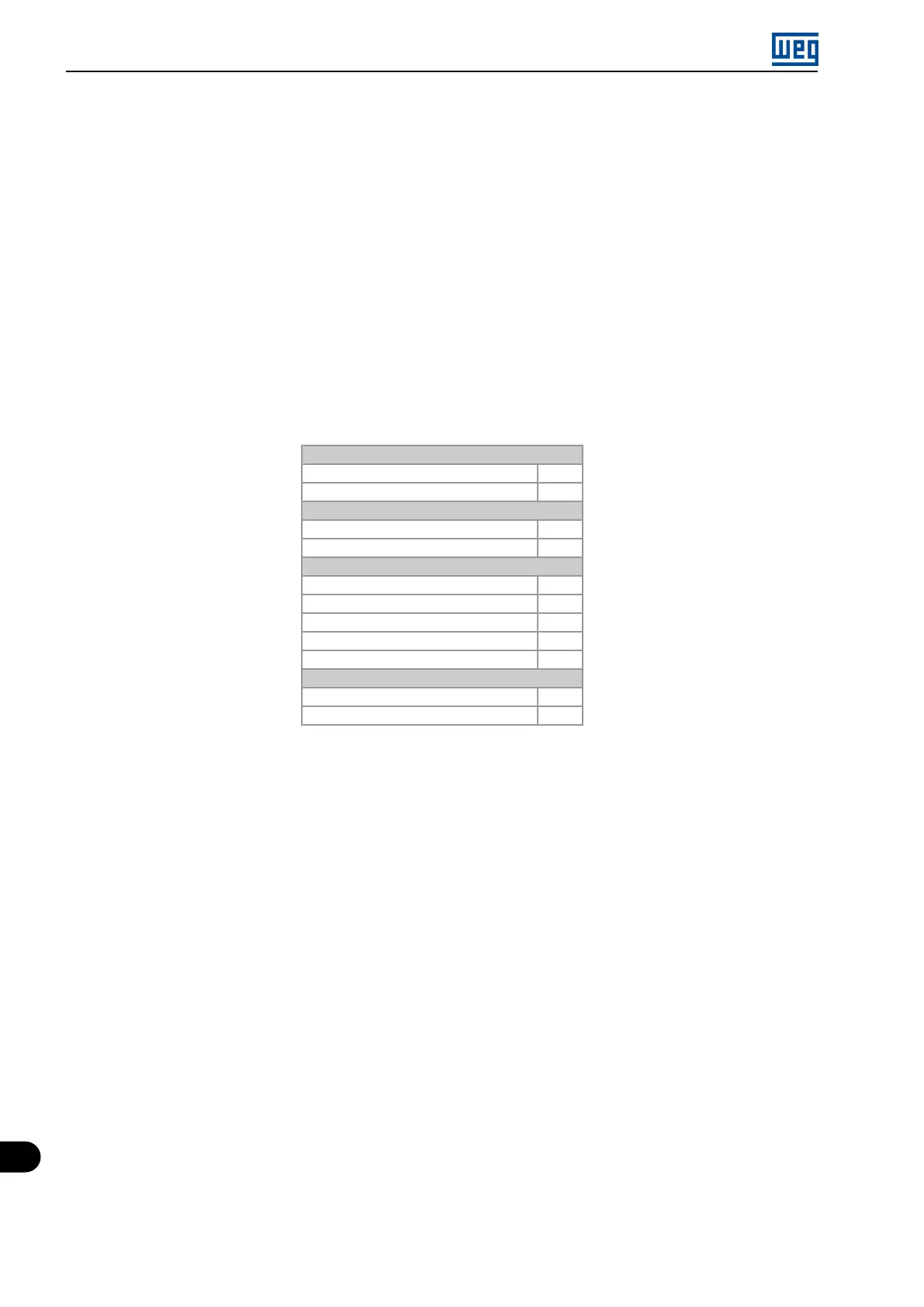
The functionalities that can be programmed in the analog and digital inputs and outputs are shown in the Table
14.1 on page 14-2.
Table 14.1: Functionalities and programming of the analog and digital inputs and outputs
Analog Inputs AI1 (P231) and AI2 (P236)
Control Setpoint = 16
Process Variable = 17
Analog Outputs AO1 (P251) and AO2 (P254)
Control Setpoint = 29
Process Variable = 30
Digital Inputs DI2 (P264) to DI4 (P266)
Manual / Automatic PID (DI2) = 51
Increase Setpoint Command (PE) (DI3) = 52
Decrease Setpoint Command (PE) (DI4) = 53
1
st
DI of the Control Setpoint (DI3) = 54
2
nd
DI of the Control Setpoint (DI4) = 55
Digital Outputs DO1 (P275) to DO4 (P278)
Process Variable Low Level (A760/F761) = 46
Process Variable High Level (A762/F763) = 47
The control setpoint source of the PID controller is defined in parameter P920, and it may be: via parameter P911,
which can be changed via HMI (or communication networks); via analog input AI1 or AI2, being parameter P231
(AI1) or P236 (AI2) previously programmed to 16 = Control Setpoint so that it is enabled for operation; via Electronic
Potentiometer (EP) through increase and decrease commands in digital inputs DI3 and DI4, being parameter P265
(DI3) previously programmed to 51 = Increase Setpoint Command (EP) and P266 (DI4) to 52 = Decrease Setpoint
Command (EP); via logical combination of digital inputs, with the selection of up to four control setpoints, being
parameter P265 (DI3) previously programmed to 53 = 1
st
DI for Control Setpoint and P266 (DI4) to 54 = 2
nd
DI for
Control Setpoint.
The value of the present control setpoint of the PID controller (P911) can be indicated via analog output AO1 or
AO2, being necessary to program P251 (AO1) or P254 (AO2) to 29 = Control Setpoint. The variable full scale is
100.0 % and corresponds to 10 V or 20 mA.
The source of the PID controller process variable is defined in parameter P921, and it can be via analog input AI1
and/or AI2, being then parameter P231 (AI1) and/or P236 (AI2) previously programmed to 17 = Process Variable.
The value of the PID controller process variable (P916) can be indicated via analog output AO1 or AO2, being
necessary to program P251 (AO1) or P254 (AO2) to 30 = Process Variable. The variable full scale is 100.0 % and
corresponds to 10 V or 20 mA.
The PID controller operation mode is defined in parameter P929, which can be manual, always automatic or via a
Manual/Automatic command through digital input DI2, being then parameter P264 (DI2) previously programmed
to 50 = Man/Auto PID Selection. Digital input DI2 programmed to PID in Manual/Automatic is active while it is at
logical level “1”, indicating automatic command, and inactive at logical level “0”, indicating manual command.
Digital outputs DO1 to DO4 can be programmed to indicated alarm/fault conditions for low level or high level of the
process variable (PV), seeing that one of the respective parameters (P275 to P278) must be programmed to 46 =
Process Variable Low Level (equivalent to PV<PVy) or 47 = Process Variable High Level (equivalent to PV>PVx).
14-2 | Micro Mini Drives